Overview
DIY Brush Cleaner with UV LEDs
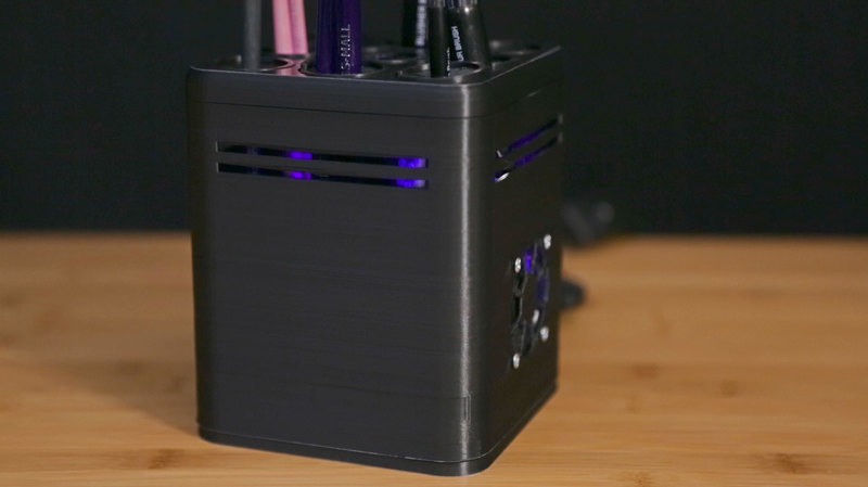
If you use brushes on a regular basis, you've probably been annoyed with how long it can take to dry the bristles. This project uses a small fan to help dry up to 9 brushes at a time. We even added Ultraviolet LEDs to help sterilize and disinfect the bristles.
Most people aren't aware that brushes used for cosmetics actually need to be sterilized to prevent bacteria from growing on bristles.
Ultraviolet photons harm the DNA molecules of living organisms in different ways. In one common damage event, adjacent thymine bases bond with each other, instead of across the "ladder". This "thymine dimer" makes a bulge, and the distorted DNA molecule does not function properly.
Our UV/UVA 400 nm LEDs causes distinct mutations in bacteria and enough UV light will kill bacteria. UV light is often used to sterilize equipment and even water.
Double-Ended brushes
We also solved the problem of damaging double-ended bristles. A detachable ring holds variable sized brushes and allows you to easy push brushes in from the side via a slit with out fraying the bristles.
Muti-Material Design
The ring holder is dual printed in PLA and NinjaFlex, so the flaps can easy bend to accommodate different brush sizes. The ring securely snaps into the grooves on top of the box. It can even hold two brush at a time to maximize space on the brush box.
Prerequisite Guides
We suggest walking through the following tutorials to get a better understanding of LEDs and soldering.
Parts, Tools and Supplies
Adafruit’s UV LEDs, PowerBoost and our enclosure design, makes it easy to build your UV brush dryer.
You'll need:
- 15 UV LEDs
- 15 100-ohm resistors
- half-size perma-proto
- Powerboost 500 Basic or Powerboost 500C
- USB Power Only Cable with Switch
- 5V 1A USB Port power supply
- 2500mAh Lithium Ion Polymer Battery
- silicone wire in red and black
- soldering iron and solder
- wire strippers
- diagonal flush snips
- helping third hand tool
- Panavise
- 2 M3x.5x6mm phillips flat head screws
- 4 M3 x.5x20mm phillips flat head screws and nuts
- 4 M2.5x.5x5mm phillips flat head screws
- PC Fan
Page last edited March 08, 2024
Text editor powered by tinymce.
3D Printing
Materials & Slice Settings
This project utilizes the flexibility of TPU materials and 3D printers with dual extrusion capabilities. If your 3D printer isn't capabile of dual extrusion, you could print the pieces separately and glue them together. Reference the slice settings in the table below – We're using Simplify3D to slice the parts.
|
brushBox-stopSM.stl brushBox-stopLG.stl BrushBox-btm.stl BrushBox-mid.stl |
PLA 225c extruder NinjaFlex 235c extruder 40mm/s print speed |
The top part of the box takes around 4 hours to print.
|
Make supports easier to remove
Some of the parts in this project will require support material. To prevent supports from bonding to the parts we used the following settings on supports.
- Support infill percentage is set to 20% with the pillar resolution at 4mm.
- Make sure to use at least a .3mm horizontal offset from the part for support separation.
- Set upper and lower vertical separation layers to 1 and drop dense infill percentage to 50%.
Support removal
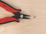
A pair of flat pliers can help remove support material. Use the tips to grip onto the material and loosen the bond for easy removal.
The rubber stopper can be dual extruded or printed in two pieces and then glued together. Use a .4mm nozzle to print the small ninjaflex details.
Speed up print times by using a large .6mm or .8mm nozzle to print the mid section of the box.
Page last edited March 08, 2024
Text editor powered by tinymce.
Circuit Diagram
Wired Connections
The circuit diagram above shows how the components will be wired together. This won't be 100% exact in the actual circuit but it's a very close approximation.
Arrange the LEDs evenly across the two sides of the boards. It's helpful (but not strictly necessary) to keep all the LEDs in the same orientation (all long legs towards one side). Here's an LED layout diagram:
USB 5V Power
This circuit will be powered by the Adafruit Powerboost via 5V power supply. You can optionally connect a USB battery pack into the Adafruit Powerboost to make it portable. To turn on and off the circuit, you can use a USB cable with a on/off switch.
Page last edited March 08, 2024
Text editor powered by tinymce.
Assemble
Prep Resistor
Use flat pliers to bend the resistor legs to fit them into the perma-proto breadboard through holes.
LED layout
Refer to the circuit diagram to arrange the LEDs and resistors in place.
Tac parts in place
We'll need to filp the perma-proto board upside down to solder the LEDs and resistors. Use small pieces of tack to hold the parts in place while soldering.
Solder LEDs
Carfully double check that each part is flush against the perma-proto and begin soldering each leg.
Cut LED legs
Grip the legs with flat pliers and then cut each off with flush cutters.
Tin, strip and solder wires
Measure and cut the wires for power and ground, then strip and tin the them to easily solder to the through holes on the perma-proto.
Cut Trace
To prevent ground from bypassing the resistor, we'll need to cut a trace on the row to separate the ground from the LED from the ground to the wire.
Solder external power and ground wires
Lay the PowerBoost and Perma-Proto board on the bottom part of the brush box and measure the wire length needed for the power and ground rails on the Perma-Proto.
Connect rails
Run power and ground to both sides of the Perma-Proto board by soldering each rail together.
Check connects
Inspect each through hole from any bridging. You can use a solder sucker if any connections are bridged.
Solder PowerBoost
Tin the 5V and G pads on the PowerBoost and connect the + and - wires on the Perma-Proto.
Solder Fan
Connect the + and - pads on the PowerBoost to the red and black wires on the fan.
Tap standoffs
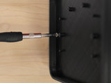
Create threads for the standoffs by creafully fastening the screws before mounting the boards. Make sure to drive the screws in as straight as possible while fastening.
Mount boards
Use M3 x .5 x 6m screws to mount the Perma-Proto board to the bottom standoffs.
Mount fan
Use #6-32 x 3/4 inch or M3 x .5 x 20MM screws with nuts to attach the fan to the grill section of the box.
Add screws from the outside of the box and add the nuts to the inside of the box to mount the fan.
Battery
To make the cleaner portable, we can add a 2500mAh lipo battery to the inside wall of the box with double stick foam tape.
Attach bottom
Align the mid part of the box so the port opening and USB port on the PowerBoost match. Snap the mid part of the box into the lid part on the bottom section of the box. You can slide the mid section in at an angle if the tolerences are tight.
Plug in USB
Connect the micro USB cable through the port opening and connect it to the PowerBoost.
Attach the USB on/off switch to the other end of the micro USB cable and test to power by plugging it into the wall or battery power bank.
Attach Top
Snap the top part of the box the rest of the box, slide it in at angle if the tolerences are too tight.
Page last edited March 08, 2024
Text editor powered by tinymce.