


Insert a #4-40 x 3/8" machine screw into the more recessed of two holes on the end of the printed battery case. Add a matching nut on the inside. This may require tweezers and a few tries!
Tighten the screw so it’s snug and doesn’t rattle, but not so tight as to crack the case.
This screw will be the negative terminal to the soldering iron.

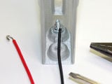

Earlier we bent hooks on the ends of the thicker power wires. Wrap the negative (–) wire hook around this first screw, then add a second nut. Cinch it down securely using small pliers.
Make sure the nuts are pinching the metal part of the wire, not the insulation. You may need to pull the insulation back a bit to ensure good contact.

Repeat with the second screw, nuts and positive (+) wire in the other hole. This one’s a little easier, since it’s closer to the surface.
Both wires should be securely held in place; they shouldn’t pivot around. If everything seems solid, secure the nuts with a tiny dot of thread lock, epoxy or E6000 glue.


Splay the ends of the power switch ever-so-slightly to provide some spring pressure, then press-fit it into the slot in the enclosure (you may need tweezers or small pliers to reach). The unconnected pin should be nearest the screw terminals…or at least, I felt this made the most sense, so the “on” direction matches the iron’s regular power switch.
Secure the switch in place from behind with some dabs of 5-minute epoxy. E6000 glue works too, but needs a few hours to reach full strength; the switch will get pushed out if you play with it too soon. DO NOT goober the switch up with tons of glue…if it seeps inside, the switch will no longer work! A bit at the ends should be plenty.
When properly installed, the tip of the switch should protrude just a millimeter or two from the surface. Set this piece ON ITS SIDE while the glue dries, or the switch might get pushed out of its socket (and then gets glued there permanently).


Add a dollop of glue to the flat underside of the PowerBoost 500 board, then angle it into place. The board will not drop straight in…lower it in sideways, catch one edge in the case, then pivot it down like closing a door. (This was to make the overall case a little slimmer.)
Make sure the USB port faces the end opening! Also, keep some pressure on the board while the glue dries, so it sits flat. Finger pressure is fine for fast-setting epoxy, otherwise improvise with whatever non-conductive implements you have around.

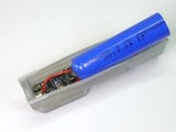


The last step, getting the battery inserted, is a little tricky. The enclosure is just flexible enough that we can squeeze the battery through the slightly-too-narrow opening.
The battery wires should point toward the USB end of the case. Push that end of the battery into the MIDDLE of the case, then gradually slide it along while pushing in the rest…the tip of the battery should “click” first, then you can pivot the full battery into place.
If the case bulges around the battery, it’s probably interference from the wires. Pivot the end of the battery back out, arrange the wires more carefully using tweezers or a toothpick, then press the battery back into place. It may take a few tries to get it just right.
If using E6000 glue or a slower-setting epoxy, set the battery case aside at least overnight…the glue needs several hours to reach full strength. Place it on its side to dry, and make sure the power switch has not been pushed out of place. If so, press it back in from behind while the glue’s still flexy.


Flick the battery switch toward the tip of the iron to engage the PowerBoost. You should see a blue LED light…if not, check the troubleshooting steps on the prior page.
You need to use both this switch AND the regular iron power switch to turn it on. If either switch is off, the iron will not heat up.
I’m not a fan of soldering irons without a stand, but in desperate times you just have to make due with what’s there. Perhaps one could get clever with a coat hanger to design a safe stand that surrounds the tip.


If you see a red LED, that means the battery is very low — below 3.2 Volts.
The nice thing about lithium-ion cells is that you can top them off any time, low battery or not. Plug in a USB microB cable to a phone- or tablet-charging wall supply, or a powered USB hub. You’ll see a yellow LED while charging, and a green LED when full. A full charge may take a couple hours.
You can use the iron while plugged into USB. There isn’t enough current to simultaneously charge the battery while soldering, but it will at least discharge more slowly.
Temper Your Expectations
You cannot change the laws of physics. Even with a mighty lithium ion battery (and the well-regarded Hakko brand), this will always be a 5(-ish) watt soldering iron. The goal here was the convenience of USB charging, and most of the limitations of the original tool are still at play. This is a small emergency back-up iron, the electronics equivalent of those temporary spare tires. As such, some things to keep in mind:
- It takes at least 45 seconds from a cold “off” state before the tip is hot enough for soldering.
- At only 5 watts, thermal recovery is going to be poor. Count to five after each solder connection before starting the next.
- It’s good for component-to-board and small component-to-wire and wire-to-wire connections. Large connections are not practical.
- Probably best with leaded solder. Lead-free requires a higher temperature.
- Both when charging and when running the iron, it’s normal for the PowerBoost to get a little warm, no harm done!

I successfully soldered 300 header pins, provided I allowed a few seconds for thermal recovery after each pin. That’s not bad!
After about 30 minutes of continuous soldering like this, when it came time to fill along the power rails, the battery could not keep up and there was insufficient heat for good connections; I switched it off at that point and plugged it in to recharge. So the iron works fast in this state, but not long.
A fresh set of AA alkaline cells, by comparison…with an initial voltage a bit over 6V, the iron heats quickly (ready in 30 seconds) and the first couple rows went well. But alkaline batteries perform poorly with high current loads…eventually managed about 250 pins, but this took over an hour due to progressively slower thermal recovery! And that’s a couple bucks worth of batteries, gone.
Nickel Metal Hydride (NiMH) cells will almost certainly outperform either in this application…they thrive under heavy loads, and with no boost converter to operate, should run longer into their discharge curve. But the downside of having to bring a separate charger just for those cells (vs. using a USB cable already on-hand) was the entire motivation for this project.


