Every facility has a conference room or other meeting space. And when the door is closed, it is always a guessing game whether the room is occupied or not. This inevitably leads to someone opening the door and disturbing what is happening inside. It could interrupt a meeting or spoil an important experiment.

Commercial sensor/indicator combinations can cost over $400 dollars. If you have many rooms, the cost could be prohibitive.

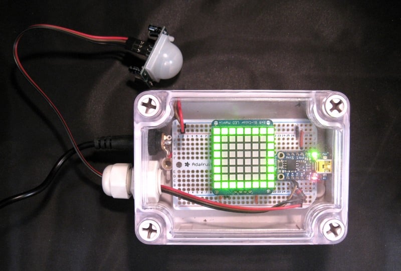
This project started as an inquiry by the Indiana University IT Department who wrote to Adafruit asking if there was a less expensive alternative to commercial units by using Adafruit's Trinket mini-microcontroller. This project is inspired by that inquiry.
The small weatherproof enclosure is a good sized enclosure for the project. The 1/2 sized Perma Proto Board fits inside the box and clears the rounded divots with a bit of modding..

The 2.1mm panel mount barrel jack is used for power - solder power wires on prior to installation (large lug is positive). Drill a 1/2 inch hole just past the cover hole. The plastic dimple was chisled to fit it in that location. Thread the jack in securing with the included plastic screw ring. A cable gland is used to run the PIR sensor wires through the enclosure keeping things weathertight. Drill a 5/8 inch hole (for the large gland, a smaller if you use the small gland) between the power jack and the other case cover hole. There is a small lip on the case - I dremeled it down a bit to have the gland fit snug. You can run penetrations through the back as an alternative if you want the look to be "cable free".

Best to make mounting holes in the back of the case if needed to screw the case into the wall. This would probably be harder later in the build given the amount of items we are putting in.

The 1/2 Perma Proto is nearly perfect. The corners should be cut just a bit on one side and the hole on that side slightly enlarged to allow it to fit snug screwed on the brass mounting hole. A short M4 screw is fitted in the enlarged hole. The board should be mounted so the screw is in the standoff furthest from the penetrations.

Wiring Diagrams


A passive-infrared sensor (PIR) is the gold standard for tracking movement in a general area. It does not provide distance like ultrasonic or other sensors but can have a wide field of view and good sensitivity to warm bodies.

A Trinket receives the signal from the PIR. When the room is occupied, the sensor tripped, Trinket will display a red X on an Adafruit 8x8 bi-color LED matrix. If there is no movement, a green square is displayed.

The function of a PIR can be found in this older tutorial by LadyAda. Also Learning Arduino Lesson 17 features this sensor.

Populating the Board

You can refer to the Fritzing diagrams on the Overview Page for the parts placement.

I used two pieces of female header, 5 pins each, to mount the Trinket to the board. This allows the Trinket to easily be removed for programming. A 4 position header mounts the display. Another couple pieces of header from the scrap box are used to steady the top end for an even mount. Socket headers are not required but make it very easy to change out components and wire underneath.
The wiring is straightforward:
  • Pin 0 on Trinket to the display I2C data line
  • Pin 2 on Trinket to the display I2C clock line
  • BAT on Trinket to the + line on the protoboard which is connected to 5 volts
  • GND on Trinket to the - line on the protoboard which is connected to power ground
  • Pin 1 on Trinket is connected to a 1500 ohm resistor to +5 volts (available at Radio Shack, Maker Shed, and other electronics outlets)
  • Pin 1 on Trinket is also connected to the PIR data line (center)
The red power line on the PIR and display goes to 5 volt + line on the protoboard
The black ground line on the PIR and display goes to the ground - line on the protoboard

Be sure you interconnect the top and bottom power busses with interconnect wires (towards the left).

I mounted pins to the power lines to plug in the power jack (upper left). I also put pins on power and Trinket Pin 1 to easily connect the PIR wire.

Double check your wiring to the diagrams and pictures.
Mount the board inside the enclosure with the screw. If it does not fit, you must take some material off the right ends and enlarge the hole for the screw.

Plug in the power from the power panel mount jack to the + and - on the board. Run a cable from the PIR to the +, -, and Pin 1 on Trinket per the Fritzing diagram. You can now plug the display in.

Leave the Trinket out as we are going to program that next.
For Trinket, you need to have a modified Arduino Integrated Development Environment (IDE) to compile and load code. Please see the tutorial Introducing Trinket for the steps necessary to set up your programming environment.
New for 2016: The Arduino IDE Version 1.6.7 and later has support for Adafruit Trinket. We suggest downloading the latest IDE from arduino.cc and the latest Adafruit libraries noted below.

Three Arduino libraries are used to facilitate programming:

  • The Arduino IDE Wire library provides I2C communications between the Trinket and the display.  The Adafruit_LEDBackpack code loads in the Wire library so we do not need to do it in the main sketch unless we want to use I2C communications for other devices.
  • The Adafruit LED Backpack library has routines to talk to the display.  This library was updated in 2016 to use the Trinket compatible Wire library.
  • The Adafruit GFX library is required to accompany the backpack library. The statement to include this library is done in the LEDBackpack library. Adafruit BusIO must also be installed manually if using an older version of the Arduino IDE (pre-1.8.10), newer versions handle this automatically with the GFX library.

Using the Adafruit libraries take up a fair amount of space but simplifies programming.

Please see the Adafruit tutorial All About Arduino Libraries for information on adding these libraries to your Arduino environment. Install the libraries into your arduinosketch/libraries directory. Restart the IDE to ensure the libraries load.

Cut and paste the following code into your IDE window:

/*************************************************** 
  Adafruit Trinket-based Room Occupancy sensor and display
  
  Featuring a Trinket 5V and the
  8x8 Bi-color LED Matrix and I2C Backpack
  
  For Trinket, this program is within 120 bytes of the maximum
    code size of 5,310 bytes.  Adding significantly more
    functionality may not be possible.  

Version 2.0 New Wire Library support for newer IDE
            Mike Barela for Adafruit Industries
 ****************************************************/

// The Adafruit_LEDBackpack library will pull in the standard Arduino 
//   Wire library and needs the Adafruit_GFX library to be installed also!
#include "Adafruit_LEDBackpack.h"

const int PIRpin = 1;    // PIR signal pin on Trinket Pin #1
uint8_t pirState = LOW;  // Stores state of the PIR sensor

Adafruit_BicolorMatrix matrix = Adafruit_BicolorMatrix();

void setup() {
  pinMode(PIRpin, INPUT); // Initial state is low
  matrix.begin(0x70);     // pass in the address
}

static const uint8_t PROGMEM   // X and square bitmaps
  x_bmp[] =
  { B10000001,
    B01000010,
    B00100100,
    B00011000,
    B00011000,
    B00100100,
    B01000010,
    B10000001 },
  box_bmp[] =
  { B11111111,
    B10000001,
    B10000001,
    B10000001,
    B10000001,
    B10000001,
    B10000001,
    B11111111 };

void loop() {
  int sense = digitalRead(PIRpin);  // Read PIR Sensor
  if(sense == HIGH) {     // If high and it was low, sensor tripped
    if(pirState == LOW) { //   and we display a red X
      matrix.clear();
      matrix.drawBitmap(0, 0, x_bmp, 8, 8, LED_RED);
      matrix.writeDisplay();
      pirState = HIGH;
    }
  } else {
    if(pirState == HIGH) {  // If low and state was high, sensor set
      matrix.clear();       //  and we sisplay a green box
      matrix.drawBitmap(0, 0, box_bmp, 8, 8, LED_GREEN);
      matrix.writeDisplay();
      pirState = LOW;
    }
  }

}

Ensure you set the Arduino IDE as follows:

Tools -> Board to: Adafruit Trinket 8MHz
Tools -> Programmer to: USBtinyISP

Press the verify checkmark icon to verify your code compiles. If it does not, check the code and the libraries. Note there are only a few bytes left in the code space so adding functionality might take up too much space. This includes adding the delay function.

Take your Trinket out of the circuit and plug it into the USB cable.

Then press the Trinket reset button on the board then quickly click the upload icon (right arrow) in the Arduino IDE. This will upload the code to the Trinket.

If you get an error on upload (and not on verify), try the sequence again. If you consistently have errors, see the Adafruit Trinket forum on steps to debug the process.

Considerations

The code space is very tight using all the libraries. More code space could be obtained by using low level I2C calls. This was done in the Space Invaders pendant tutorial. This would require additional work to get the correct calls coded and since this project works great as is, we didn't spend the extra hacking-time!

Adjustment

The PIR has two adjustment potentiometers on the back.
  1. The first adjusts the sensitivity of the sensor. You should start with a reading towards the "min" side, and adjust clockwise as necessary.
  2. The second adjusts the time the sensor stays "latched" or in the on state. When testing, leave this at the left which is a short time. Adjust clockwise for longer intervals.
Test the unit by making all the connections and the PIR is pointed away from movement or covered by a cardboard box. The green square should be displayed.
Move in front of the sensor and the red X should be displayed.
If the display does not change, check your wiring to the sensor and the potentiometers.

Once it is working, you can adjust the potentiometers to increase sensitivity and/or the delay used.

One programming note: the Arduino delay software routine cannot be used with the libraries as it adds a bit too much code. Try to adjust using the PIR potentiometers.

Mount

Mount the display box near the entrance to the room monitored. Mount the PIR sensor so it has a "field of view" of a wide area of the inside of the room. For a conference room, the table area would be best (do not aim above peoples heads).

Run power from an outlet to the display box. Ensure you have a 5 volt DC supply.
If you only want the display to show through the clear cover, you can make a mask from white paper. You can have the LED display show through the paper or cut out a square just for the display.

This guide was first published on Dec 18, 2013. It was last updated on Mar 08, 2024.