LEDs
Get creative and choose a colored pattern for your LEDs. The long terminal pin of the LED goes to the +positive pin on the Trellis PCB. Ensure your LEDs are correctly positioned to the PCB before soldering. It's also nice to check to see if your LED work by keeping a rechargeable coin cell battery for testing.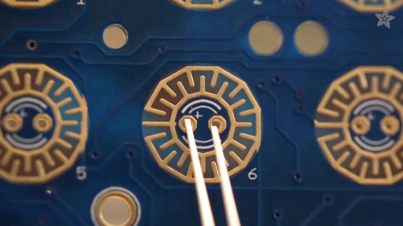

Soldering
For a clean soldering process, try to soldering the LEDs one by one, and then cutting the access terminal pins from the LEDS. For a more comfortable process, use a Panavise Jr. to keep the Trellis PCB in place while your solder. A Third Helping hand can assist you in holding the terminal pins of the LEDs in place while your solder.

The Trellis uses 5 connections that can connect to the arduino or similar micro-controller. We recommend using jumper wires for connecting to the arduino.
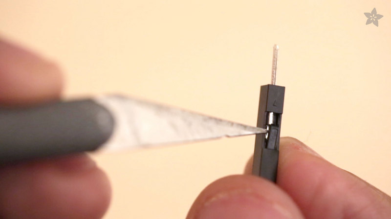
To ensure the jumper wires don't get in the way inside of the enclosure, we need to:
To ensure the jumper wires don't get in the way inside of the enclosure, we need to:
- Remove the protective guard from both sides of the jumper wires (x-acto knife helps)
- Trim one side of the jumper wire pin, leaving a small piece for the Trellis connections

You will need to carefully bend the long pin ends of the jumper wires so that they can fit into the arduino headers without getting in the way of the Trellis PCB.

Use small pieces of electrical tape to protect the exposed pins on the long jumper pins.

Below is a list of which pins will go from the Trellis PCB to the Arduino.
5V goes to the 5V power pin on the Arduino
GND goes to and GND ground pin
SCL goes to the I2C clock pin, on an Uno this is also known as A5
SDA goes to the I2C data pin, on an Uno this is also known as A4
We connect the INT interrupt pin to A2 - this pin isn't used in our demo code so you can leave it unconnected if you wish.


3D Printed Parts
The micro controller will be mounted to the bottom cover. Place the controller on top of the bottom cover and align up the mount holes to see if it fits your micro-controller. Use screws to secure the micro-controller in place.
Place the frame on top of the bottom cover and gently fit the IO ports of the micro-controller into the holes of the frame. The frame has a lip that should be closer towards the top. The frame tightly snaps to the bottom cover.

Lay the Trellis PCB on top of the tray. It should tightly snap onto the tray, exposing the connection fingers. You may need to press down the Trellis PCB to snap into the tray

Carefully place the tray on top of the frame. The Trellis PCB should be above the micro-controller, with just enough room for the jumper wires.

Add the Elastometers keypad to the top of the Trellis PCB. Align up the keypad so the pins fit into the holes of the Trellis PCB.
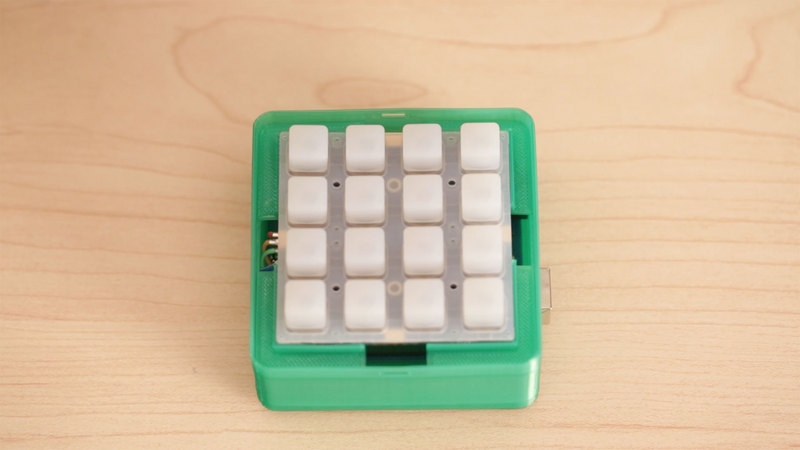
Fit the top cover into place and snap it into to close the enclosure. You may need to use flat head on the frame to securely snap the cover onto the frame.

For a tutorial on installing the Trellis Arduino Library, follow the introduction to Trellis guide for installation instructions and a demo sketch.


