Driving a LED Strip
A simple LED strip is a great example of a load. You simply control whether current is flowing through it. All you need to be concerned with is whether the control circuit can supply enough current.
These neon-like LED strips 'look' like one very big, high power LED - and they need 12V to light up!

Here we have a Gemma M0 using a PWM output (a 3.3v signal that can provide a handful of milliamps) to drive a TIP120 Darlington Pair to control an led strip (no Fritzing part for it yet, so a single LED is used as a proxy). The strip takes 12v and 0.8A... aka 800 mA.
The gain of the TIP120 is about 1000, so to get 0.8A through the strip, we need a base current of 0.8mA. Erring on the side of being generous, a 2.2K bias resistor should give a bit over 1mA of base current. That's plenty to drive the TIP120 into saturation.

Here's the circuit in action. At the top you can see the TIP120. In the bottom-left is the GemmaM0 with the ground and control connected by the black and green clips, respecively. The other alligator clip is an insulated 3rd hand holding the Gemma. On the bench below is the LED strip which fades off and on due to the ramping PWM signal.
The code running this demo is:
import time
import board
import pulseio

led = pulseio.PWMOut(board.D2, frequency=5000, duty_cycle=0)

while True:
    for i in range(100):
        if i < 50:
            led.duty_cycle = int(i * 2 * 65535 / 100)  # Up
        else:
            led.duty_cycle = 65535 - int((i - 50) * 2 * 65535 / 100)  # Down
        time.sleep(0.05)
Electromagnets, Solenoids, and Motors
These are electrically very similar: they are all inductive loads (made of a coil of wire) that can draw a moderate to high amount of current. As such they can't be controlled directly from a GPIO pin. This is where transistors come in.
An electromagnet is a coil of wire around a core of magnetic material. When current flows though the coil, a strong magnetic field is generated. I.e. it becomes a magnet. When the current stops, it ceases to be a magnet.
A solenoid is basically an electromagnet in which the core and slide back and forth inside the coil. When current flows though the coil, the core moves. It can be used to create linear motion from a current. Ever have a electric model railroad? The switches points were moved by a solenoid.
A motor is an arrangement of coils and permanent magnets such that controlling the current through the coils (done inside the motor) causes the motor's shaft to spin, thus creating rotary motion from a current.
For our purpose of turning them on and off, we can think of them as all just being an inductive load.
Simon Monk did a guide on controlling a DC motor with an Arduino. Naturally, this used a transistor.

Since a transistor is a switch, it can be driven with a PWM signal. With a motor, a higher duty cycle results is a faster rotation, i.e. higher speed.
It's important to note the diode. When a motor stops, the magnetic field collapses and induces a reverse current. That can be enough to burn out the transistor. The diode serves to drain off that current harmlessly. Whenever you are controlling a motor or other inductive load, you must have a diode across it like this.

Motor H bridge
The above motor controller can turn the motor on and off, as well as control its speed, but it can only make it spin in one direction.
To control the direction of the motor as well, it can be driven using an arrangement of transistors called an H-bridge, shown below. Notice the resistors between each input switch and transistor base. These limit the current flowing through the base to just enough to drive it into saturation. Also, there is a diode between the pairs of collectors and power & ground. These allow the current generated when the motor stops to be drained away harmlessly. Without them the reverse current could blow out the transistors, as mentioned earlier.


Here's the schematic of an H-Bridge motor driver. Notice the use of PNP Transistors at the top (which connect the motor to Vcc) and NPN transistors at the bottom (which connect it to ground). By enabling diagonally opposite pairs of transistors the motor can be spun in either direction by controlling the direction which current flows through it.
Below is a breadboard layout.
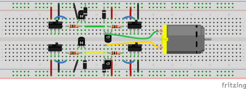
That's a fair number of components which take up a fair bit of space. Thankfully, you can get two of these packaged neatly onto a 16-pin chip: the DRV8833 which is used on the CRICKIT. Technically the DRV8833 uses FET transistors but the operation of the circuit is identical.
One handy feature of an H-bridge is that not only can it control forward and reverse operation of the motor, but it also provides coast (the motor spins freely) and brake (the motor resists rotation) modes.
See this post on robotroom.com and the DRV8833 datasheet for more details.


