These steps apply only to the total conversion beam prop. For the talking computer, you can skip ahead.

Install Handle
Place the half of the blaster over the top of the handle.
Insert the various cables through the large hole in the half of the blaster.


Install PCB Mount
Place the PCB mount over the mounting holes of the blaster and handle. Feather’s USB port faces toward the front of the prop.
While holding in place, insert and fasten 3x M3x12mm long screws to secure the PCB mount.
The screws secure the PCB mount, blaster and handle together.
Note: there is a fourth mounting hole, but it’s obscured by the Feather PCB so we’ll just skip it. Three screws should suffice, or you can use a few small dabs of glue to help reinforce the body-to-handle connection.


Install LED to Holder
Fit the 10mm LED through the clip of the holder inside the half of the blaster.
If the LED doesn’t press-fit firmly, a dot of glue will help hold this in place.

Install Speaker
Peel the adhesive tab and press the speaker face-down into the cavity inside the half of the blaster.

Install Slide Switch
Insert the body of the slide switch to the built-in holder inside the half of the blaster.

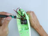
Connect Amplifier
Plug in the cable from the amplifier to the accompanying connector on the Feather.


Connect Slider Potentiometer
Plug in the cable from the slider potentiometer to the accompanying connector on the Feather.

Connect Pushbutton
Plug in the cable from the push button to the accompanying connector on the Feather.


LED Trigger Test
Use the slide switch to turn on the Feather. Use the pushbutton to test out the circuit.


Final Build
Place the top half over the body (magnets will click them together) to finish the build.