Right Angle Jumper Cables
For wiring the buttons, we're going to use female/male jumper cables. We'll need to slim these down so they fit inside the enclosure.
Remove the plastic covers from the female end to expose the connector. Bend the connector using flat pliers to make a right angle cable. Add a piece of shrink tubing to insulate the exposed connector.
Cut off the other end of the jumper cable and strip the end using wire strippers. Tin the stranded wires to make it easier to insert into breakout boards.

Start and Select
Place the start/select PCB over the bottom enclosure part. Line up the hole in the center of the PCB to the post near the left side of the bottom enclosure part. Measure the length of wire needed to connect to the Pi GPIO. Cut wire and prep to make it a right angle jumper cable.
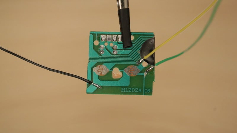
Wire Start/Select PCB
Remove PCB from enclosure and secure to helping third hand. Solder the three jumper wires to the pads on the PCB.

Prep A, B, X, Y and R Wires
Place the PCB over the enclosure and line up the center hold with the post on the right side. Measure length of wire needed to connect PCB to Pi GPIO. Add a bit extra slack for moverability. Cut six pieces of jumper wires and prep them to be right angled following the steps above.

Wire A, B, X, Y and R
Remove PCB from enclosure and secure to helping third hand. Carefully solder the jumper wires to the tin spots on the button PCBs.

L Shoulder Button
Insert L shoulder PCB to the holder on the left side and measure the length of wire needed. Prep two jumper wires and solder them to the pins on the PCB.

Wired PCBs
The button PCBs will have different lengths of wire. The colored jumper cables helps differentiate wire connections.
Prep Button PCB base
Apply mounting putty the surface of the two base platforms where the PCBs rest - This will keep the PCBs from slipping.

Mount Start/Select PCB
Place the start/select PCB back onto the enclosure part with post fitted through center hole. Press PCB down to secure in place.

Mount A, B, X, Y and R PCB
Place the button PCB onto the enclosure with post fitted through center hole. Press PCB down to secure in place. Double check orientation is correct.
R shoulder button is fitted into the shoulder holder. Slide into place with traces facing out.

Install L Shoulder PCB
Insert the L Shoulder PCB into the holder on the left side of the enclosure with traces facing out.


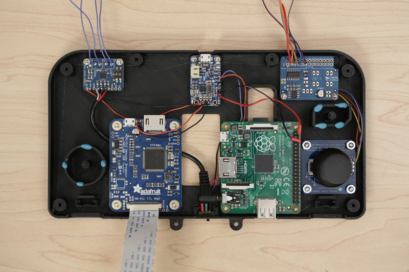
Connect Jumpers to Pi
Follow the Pi GPIO wiring diagram and carefully plug each jumper wire to the GPIO pins.
Some jumper cables may need to over lap each other to fit properly. Avoid cables from blocking any other components. Double check your work.


