
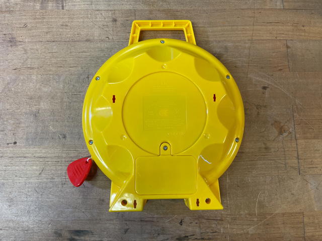


Open the Case
Flip the See N Say over and unscrew the battery door, then remove the batteries.
Unscrew the seven screws and set them aside, then carefully pull open the case.


Sound Button Press
Most of the pull string mechanism is there to spin the selector arrow, the only part in the front case section that causes sounds to play is the small plastic nub on the central gear -- when the string is fully pulled out that nub raises up slightly and presses the associated rubber dome switch.


Button Pad
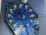
The electronics are all on a single PCB. The center of the PCB is a set of 12 open contact buttons that are closed by pressing rubber domes with conductive pills in them. This is the same as what you'll find in a video game controller or rubber dome switch keyboard.
Carefully remove the rubber ring, then unscrew the two screws holding the PCB in place.


Glue Removal
You'll desolder the battery wires and speaker wires from the board, since we only need the button contacts and common contact test points, the rest of our electronics will be transplanted.
Flip over the PCB and you'll see the battery wires and speaker wires have hot glue blobs on them for strain relief.
Dab on some isopropyl alcohol to loosen and then remove the hot glue.


Wire Desoldering
Heat the two speaker wire solder points and the two battery wire solder points with a soldering iron while gently pulling down on the wires with tweezers or pliers.
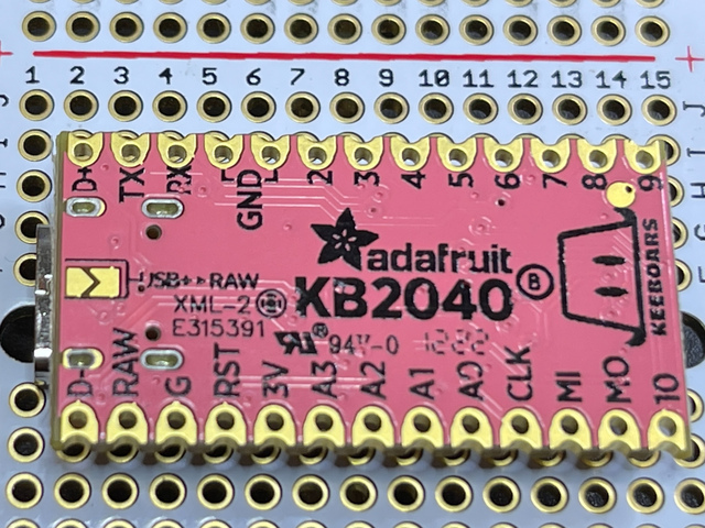


KB2040 Prep
Jumper the USB+ > RAW pads with some solder. This will allow us to use 5V power from the MiniBoost (which takes the ~3V AA battery input and converts it). The I2S works better with 5V as well.
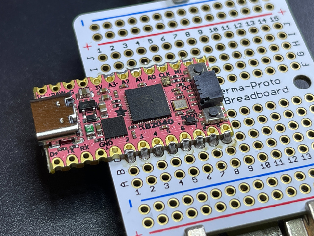


KB2040 on PermaProto
Solder the KB2040 to the PermaProto board as shown.
You can use the castellated pads instead of adding pins if you like, this keeps it a bit more svelte.


Amp
Solder the MAX98357A I2S amplifier board to the PermaProto as shown.
You can use bare header pins as shown to keep things low profile.


MiniBoost Prep
Add some Kapton tape or electrical tape to insulate the MiniBoost mounting hole from the PermaProto.
This isn't normally necessary, but since we're keeping it super low profile, the mounting hole plating could short some pads otherwise.
Solder the MiniBoost to the PermaProto board.


Button Pad Wiring
Conveniently, there is a test pad next to each pair of switch contacts! Solder a thin wire, approximately 5" long, to each test pad as well as the GND pad.
Wire wrap wire, enamel coated magnet wire, and 28-30 gauge silicone covered wire all work well for this. Make an effort to run the wires inward so they won't disrupt the elastomer pad.


Button Connections
Place the button board and PermaProto into the back case temporarily to get a sense of the wire lengths and trim/strip as needed.
Then, one-by-one, feed a wire through the PCB's center hole and solder the twelve button wires to their respective GPIO pins, as well as the GND from the button board to the PermaProto.


KeeBoar Ground
Since the KB2040 is hanging off the edge of the board for space considerations, you'll need to free-wire its GND to the PermaProto. Run a wire from each side to the ground rails, so both sides of the PermaProto have common ground.


Battery Box Connections
Place some insulating tape over the battery box contacts so nothing is shorted to the PermaProto accidentally.
Solder the battery box ground (black) wire to PermaProto ground rail, and the battery box +V (red) wire to the Vin pad on the MiniBoost.
To prevent any issues in case the KB2040 is plugged into USB when the batteries are also supplying power, solder a Shottky diode from MiniBoost 5V to PermaProto power rail as shown.
Run a wire from one PermaProto power rail to the other, then wire the KB2040 RAW pin to the PermaProto power rail.


Power Enable Switch
You'll turn the toy on and off with a DPST toggle switch that shorts the MiniBoost enable pin to ground.
Solder one wire to the center common pin and another to either outer pin of the switch.
Ream out the packaging key hole a bit and then insert the switch through it. Tighten the nut from the other side to secure.
Solder the center wire to ground and the other wire to the MiniBoost En pin.


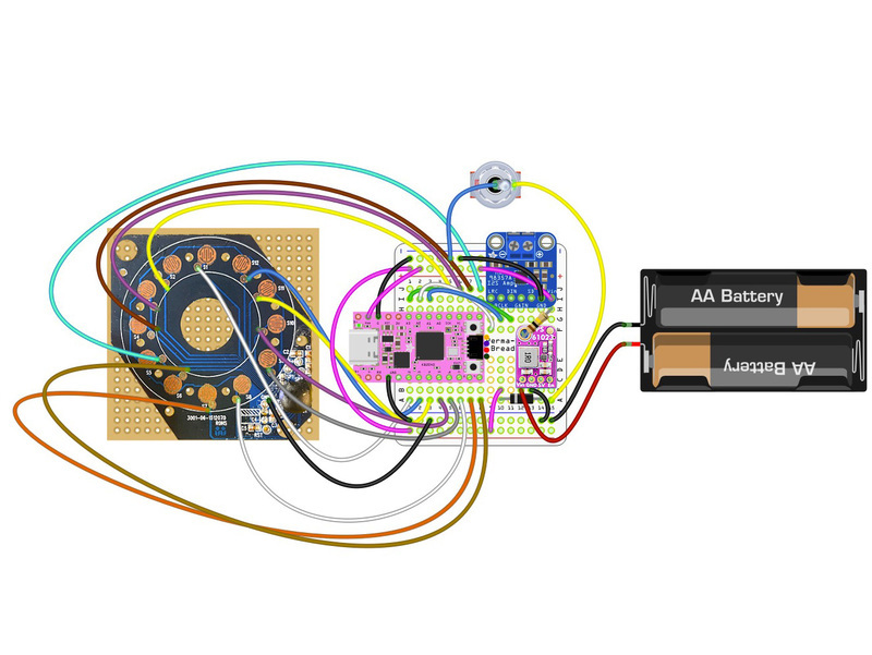
I2S Audio Amp Wiring
Wire the MAX 98357A I2S Amp as follows:
- KB2040 A1 to BCLK (bit clock)
- KB2040 A2 to LRC (word select)
- KB2040 A3 to DIN (data)
- Ground to GND
- 5V power rail (from MiniBoost output post-diode) to Vin
- Speaker wires to speaker output
Place the elastomer button pad ring back on the PCB, pulling the rubber nub legs through their respective holes.

Test It
This is a great time to test it out! Put the two AA batteries back in the case, flip on the toggle switch, and press each rubber dome button to hear the audio.


Secure the Brain
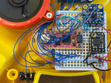
Use double-stick foam tape to secure the PermaProto and elecronics to the inside of the case on the back of the battery box.
Screw the original PCB back in place.


Wire Dressing
Use Kapton tape to secure wiring in any places where it may be a bit loose in order to avoid any snags.

Close the Case
Pull and hold the pull-string to get the arced gear out of the way (it will slide under the transplanted PermaProto board during operation), then close the case.
Release the string slowly to make sure there are no obstructions.


Screw the Case in Place
Refasten the seven case screws, then insert two AA batteries and close the battery door, securing it with the captive screw.


