Use CircuitPython 7.0.0 or newer for this project.
Revised code will be required for CircuitPython 8 on Espressif microcontrollers.

CircuitPython 7 adds the qrio module, which can decode QR codes from images grabbed with compatible cameras like the OV2640. (What is a QR code?)

These demos are designed to work with the Espressif Kaluga development kit, which comes with a compatible camera, can connect via WiFi to Adafruit IO, and has plenty of RAM to store the images for analysis.

This guide includes three demos:

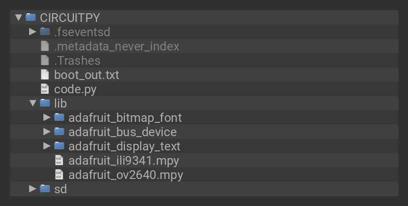
  • Scan To REPL: Each scanned and decoded barcode is printed in the REPL, so you can see it in mu or other compatible software
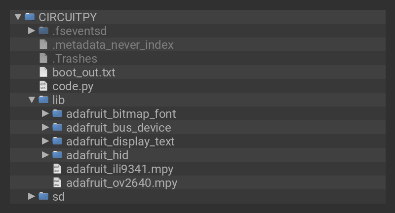
  • Scan To USB HID: Each scanned and decoded barcode is typed into the connected host computer using a virtual keyboard
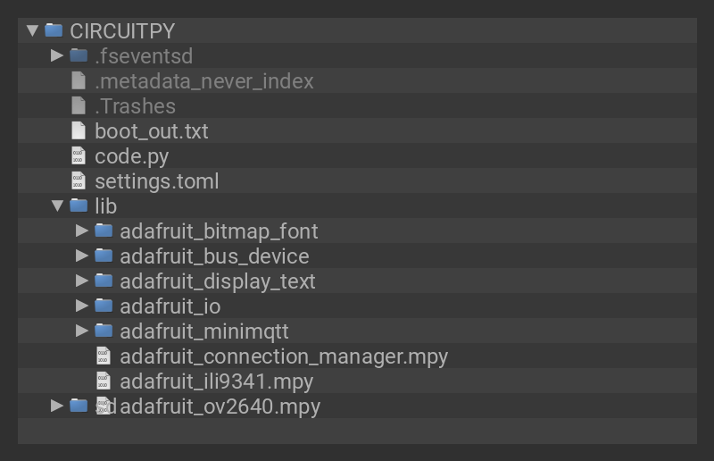
  • Scan To Adafruit IO: Each scanned and decoded barcode is sent to Adafruit IO, where you can view it on a dashboard or connect it to triggers.

Additionally, each demo uses the Kaluga's LCD screen to show the live image in greyscale as well as the last scanned code.

For the Scan To Web demo, we've made sure the code works with the free version of Adafruit IO, so give it a try even if you haven't subscribed to IO+ yet.

Creating QR Codes

There are lots of sites & services to generate QR codes. This one seems pretty no-nonsense.

If you have Python installed on your host computer, you can use the Adafruit miniQR Library to show QR codes in a terminal window.

If you use the Duck Duck Go search engine, you can search for "qr" + your terms, like so.

Overview of QR Scanning

Create a QR Decoder object

You'll want to create the QR Decoder object just once in your program, if possible. When creating it, pass in the width and height of the image that you will later decode.

qrdecoder = qrio.QRDecoder(cam.width, cam.height)

Capture a greyscale or YUV image

qrio uses only the luminance, greyscale, or "Y" value of pixels (determined by the PixelPolicy value passed to its decode function). For the OV2640 camera, placing it in YUV mode and then using the EVEN_BYTES policy gets the correct data.

cam.colorspace = adafruit_ov2640.OV2640_COLOR_YUV
bitmap = displayio.Bitmap(cam.width, cam.height, 65536)

Retrieve decoded strings

A QR code is usually ASCII, but the result of decoding with qrio is a byte string "payload" and an encoding name. If it is ASCII or UTF-8, you can decode it with the decode method; if that fails, you can turn it into the ASCII representation of the byte string, which will print like b"...":

    for row in qrdecoder.decode(bitmap, qrio.PixelPolicy.EVEN_BYTES):
        payload = row.payload
        try:
            payload = payload.decode("utf-8")
        except UnicodeError:
            payload = str(payload)
        print(payload)

Limitations of QR Scanning

To keep the program more responsive, the image is captured at a limited 160x120 resolution. This puts a limit on how complex the QR code can be, because each dot within the QR code needs to be at least a couple of pixels big in the recorded image.

Many OV2640 cameras don't focus clearly on close objects, and have trouble taking properly exposed pictures of LCD and OLED screens. QR codes 75 to 100mm (3" to 4" inches) across printed on card stock seem to work best at a scanning distance from 150mm to 300mm (6" to 12"), while scanning from a phone screen is frustrating and rarely works.

A "fish-eye" or wide-angle lens will distort the QR code in a way that qrio doesn't correct for. You need a normal or telephoto lens to scan QR codes. If straight lines don't look straight in your camera, it's not going to work.

Parts

USB Type A Plug Breakout Cable with Premium Female Jumpers
If you'd like to connect a USB-capable chip to your USB host, this cable will make the task very simple. There is no converter chip in this cable! Its basically a...
$1.95
In Stock
USB Type A Extension Cable
This handy USB extension cable will make it easy for you to extend your USB cable when it won't reach. The connectors are gold plated for years of reliability. We use these handy...
Out of Stock
Text image that reads "IO+"
The all-in-one Internet of Things service from Adafruit you know and love is now even better with IO+. The 'plus' stands for MORE STUFF! More feeds, dashboards,...
$99.00
In Stock
Use CircuitPython 7 for the code in this guide! Revised code will be required for CircuitPython 8.

Are you new to using CircuitPython? No worries, there is a full getting started guide here.

Adafruit suggests using the Mu editor to edit your code and have an interactive REPL in CircuitPython. You can learn about Mu and installation in this tutorial.

Download the Project Bundle

Your project will use a specific set of CircuitPython libraries and the code.py file. In order to get the libraries you need, click on the Download Project Bundle link below, and uncompress the .zip file.

Drag the contents of the uncompressed bundle directory onto your board's CIRCUITPY drive, replacing any existing files or directories with the same names, and adding any new ones that are necessary.

Folder
# SPDX-FileCopyrightText: Copyright (c) 2021 Jeff Epler for Adafruit Industries
#
# SPDX-License-Identifier: Unlicense

"""
This demo is designed for the Kaluga development kit version 1.3 with the
ILI9341 display.
"""

from ulab import numpy as np
from terminalio import FONT
import board
import busio
import displayio
import qrio
import adafruit_ov2640
from adafruit_display_text.bitmap_label import Label
from adafruit_ili9341 import ILI9341

print("Initializing display")
displayio.release_displays()
spi = busio.SPI(MOSI=board.LCD_MOSI, clock=board.LCD_CLK)
display_bus = displayio.FourWire(
    spi, command=board.LCD_D_C, chip_select=board.LCD_CS, reset=board.LCD_RST
)
display = ILI9341(display_bus, width=320, height=240, rotation=90)

print("Initializing camera")
bus = busio.I2C(scl=board.CAMERA_SIOC, sda=board.CAMERA_SIOD)
cam = adafruit_ov2640.OV2640(
    bus,
    data_pins=board.CAMERA_DATA,
    clock=board.CAMERA_PCLK,
    vsync=board.CAMERA_VSYNC,
    href=board.CAMERA_HREF,
    mclk=board.CAMERA_XCLK,
    mclk_frequency=20_000_000,
    size=adafruit_ov2640.OV2640_SIZE_QQVGA,
)
cam.flip_x = False
cam.flip_y = False
cam.colorspace = adafruit_ov2640.OV2640_COLOR_YUV

qrdecoder = qrio.QRDecoder(cam.width, cam.height)
bitmap = displayio.Bitmap(cam.width, cam.height, 65536)

# Create a greyscale palette
pal = displayio.Palette(256)
for i in range(256):
    pal[i] = 0x10101 * i

label = Label(
    font=FONT,
    text="Scan QR Code...",
    color=0xFFFFFF,
    background_color=0x0,
    padding_top=2,
    padding_left=2,
    padding_right=2,
    padding_bottom=2,
    anchor_point=(0.5, 1.0),
    anchored_position=(160, 230),
)
# Show the camera image at 2x size
g1 = displayio.Group(scale=2)
view = np.frombuffer(bitmap, dtype=np.uint8)
tg = displayio.TileGrid(
    bitmap,
    pixel_shader=pal,
)
tg.flip_y = True
g1.append(tg)
g = displayio.Group()
g.append(g1)
g.append(label)
display.root_group = g
display.auto_refresh = False

old_payload = None
while True:
    cam.capture(bitmap)

    for row in qrdecoder.decode(bitmap, qrio.PixelPolicy.EVEN_BYTES):
        payload = row.payload
        try:
            payload = payload.decode("utf-8")
        except UnicodeError:
            payload = str(payload)
        print(payload)

    # Clear out the odd bytes, so that the bitmap displays as greyscale
    view[1::2] = 0
    bitmap.dirty()
    display.refresh(minimum_frames_per_second=0)

Once the code is uploaded, the program will automatically start and display a greyscale capture from the camera.

Hold a printed QR code in front of the camera at a distance of about 6". The scanned QR code will be shown on the LCD and also in the REPL.

If something goes wrong, you can use the REPL to diagnose the problem.

Use CircuitPython 7 for the code in this guide! Revised code will be required for CircuitPython 8.

Are you new to using CircuitPython? No worries, there is a full getting started guide here.

Adafruit suggests using the Mu editor to edit your code and have an interactive REPL in CircuitPython. You can learn about Mu and installation in this tutorial.

Download the Project Bundle

Your project will use a specific set of CircuitPython libraries and the code.py file. In order to get the libraries you need, click on the Download Project Bundle link below, and uncompress the .zip file.

Drag the contents of the uncompressed bundle directory onto your board's CIRCUITPY drive, replacing any existing files or directories with the same names, and adding any new ones that are necessary.

Folder
# SPDX-FileCopyrightText: Copyright (c) 2021 Jeff Epler for Adafruit Industries
#
# SPDX-License-Identifier: Unlicense

"""
This demo is designed for the Kaluga development kit version 1.3 with the
ILI9341 display.  Your secrets.py must be populated with your wifi credentials
and your Adafruit IO credentials.
"""

from ulab import numpy as np
from terminalio import FONT
import board
import busio
import displayio
import qrio
import adafruit_ov2640
from adafruit_display_text.bitmap_label import Label
from adafruit_ili9341 import ILI9341
import usb_hid
from adafruit_hid.keyboard import Keyboard
from adafruit_hid.keyboard_layout_us import KeyboardLayoutUS

print("Initializing display")
displayio.release_displays()
spi = busio.SPI(MOSI=board.LCD_MOSI, clock=board.LCD_CLK)
display_bus = displayio.FourWire(
    spi, command=board.LCD_D_C, chip_select=board.LCD_CS, reset=board.LCD_RST
)
display = ILI9341(display_bus, width=320, height=240, rotation=90)

print("Initializing camera")
bus = busio.I2C(scl=board.CAMERA_SIOC, sda=board.CAMERA_SIOD)
cam = adafruit_ov2640.OV2640(
    bus,
    data_pins=board.CAMERA_DATA,
    clock=board.CAMERA_PCLK,
    vsync=board.CAMERA_VSYNC,
    href=board.CAMERA_HREF,
    mclk=board.CAMERA_XCLK,
    mclk_frequency=20_000_000,
    size=adafruit_ov2640.OV2640_SIZE_QQVGA,
)
cam.flip_x = False
cam.flip_y = False
cam.colorspace = adafruit_ov2640.OV2640_COLOR_YUV

print("Initializing USB")
keyboard = Keyboard(usb_hid.devices)
keyboard_layout = KeyboardLayoutUS(keyboard)  # We're in the US :)

qrdecoder = qrio.QRDecoder(cam.width, cam.height)
bitmap = displayio.Bitmap(cam.width, cam.height, 65536)

# Create a greyscale palette
pal = displayio.Palette(256)
for i in range(256):
    pal[i] = 0x10101 * i

label = Label(
    font=FONT,
    text="Scan QR Code...",
    color=0xFFFFFF,
    background_color=0x0,
    padding_top=2,
    padding_left=2,
    padding_right=2,
    padding_bottom=2,
    anchor_point=(0.5, 1.0),
    anchored_position=(160, 230),
)
# Show the camera image at 2x size
g1 = displayio.Group(scale=2)
view = np.frombuffer(bitmap, dtype=np.uint8)
tg = displayio.TileGrid(
    bitmap,
    pixel_shader=pal,
)
tg.flip_y = True
g1.append(tg)
g = displayio.Group()
g.append(g1)
g.append(label)
display.root_group = g
display.auto_refresh = False

i = 0
spin = ".oOo"
old_payload = None
while True:
    cam.capture(bitmap)

    for row in qrdecoder.decode(bitmap, qrio.PixelPolicy.EVEN_BYTES):
        payload = row.payload
        try:
            payload = payload.decode("utf-8")
        except UnicodeError:
            payload = str(payload)
        if payload != old_payload:
            label.text = payload
            keyboard_layout.write(payload)
            old_payload = payload

    # Clear out the odd bytes, so that the bitmap displays as greyscale
    view[1::2] = 0
    bitmap.dirty()
    display.refresh(minimum_frames_per_second=0)

Once the code is uploaded, the program will automatically start and display a greyscale capture from the camera.

Hold a printed QR code in front of the camera at a distance of about 6". The scanned QR code will be shown on the LCD and also typed into an attached host computer via USB.

If something goes wrong, you can use the REPL to diagnose the problem.

Use CircuitPython 7 for the code in this guide! Revised code will be required for CircuitPython 8.

Are you new to using CircuitPython? No worries, there is a full getting started guide here.

Adafruit suggests using the Mu editor to edit your code and have an interactive REPL in CircuitPython. You can learn about Mu and installation in this tutorial.

Set up the IO Feed

Create a feed called "barcode". (You can choose another feed name but you'll need to make sure that Adafruit IO's "key" for the feed matches what you use in your CircuitPython program!)

You can also add this Feed to a Dashboard, if you want to show it together with information from other Feeds.

Secrets File Setup for Adafruit IO

If you don't have a secrets.py file in your CIRCUITPY drive yet, create one and add the information about your wifi connection.

Then, add the following code to your secrets.py file, replacing _your_adafruit_io_username with your Adafruit IO username.

Then, replace _your_big_huge_super_long_aio_key_ with your Adafruit IO Active Key.

secrets = {
    'ssid' : '_your_wifi_ssid_',
    'password' : '_your_wifi_password_',
    'aio_username' : '_your_adafruit_io_username_',
    'aio_key' : '_your_big_huge_super_long_aio_key_',
}

Make sure you save this file before proceeding as secrets.py in the root directory of your board CIRCUITPY drive.

Download the Project Bundle

Your project will use a specific set of CircuitPython libraries and the code.py file. In order to get the libraries you need, click on the Download Project Bundle link below, and uncompress the .zip file.

Drag the contents of the uncompressed bundle directory onto your board's CIRCUITPY drive, replacing any existing files or directories with the same names, and adding any new ones that are necessary.

Folder
# SPDX-FileCopyrightText: Copyright (c) 2021 Jeff Epler for Adafruit Industries
#
# SPDX-License-Identifier: Unlicense

"""
This demo is designed for the Kaluga development kit version 1.3 with the
ILI9341 display.  Your secrets.py must be populated with your wifi credentials
and your Adafruit IO credentials.
"""

import ssl
from secrets import secrets
from ulab import numpy as np
from terminalio import FONT
import board
import busio
import displayio
import qrio
import socketpool
import wifi
import adafruit_ov2640
from adafruit_display_text.bitmap_label import Label
from adafruit_ili9341 import ILI9341
from adafruit_io.adafruit_io import IO_MQTT
import adafruit_minimqtt.adafruit_minimqtt as MQTT

# To change the name of the feed on adafruit_io, just modify this string:
feed_name = "qrstring"

print("Initializing display")
displayio.release_displays()
spi = busio.SPI(MOSI=board.LCD_MOSI, clock=board.LCD_CLK)
display_bus = displayio.FourWire(
    spi, command=board.LCD_D_C, chip_select=board.LCD_CS, reset=board.LCD_RST
)
display = ILI9341(display_bus, width=320, height=240, rotation=90)

print("Initializing camera")
bus = busio.I2C(scl=board.CAMERA_SIOC, sda=board.CAMERA_SIOD)
cam = adafruit_ov2640.OV2640(
    bus,
    data_pins=board.CAMERA_DATA,
    clock=board.CAMERA_PCLK,
    vsync=board.CAMERA_VSYNC,
    href=board.CAMERA_HREF,
    mclk=board.CAMERA_XCLK,
    mclk_frequency=20_000_000,
    size=adafruit_ov2640.OV2640_SIZE_QQVGA,
)
cam.flip_x = False
cam.flip_y = False
cam.colorspace = adafruit_ov2640.OV2640_COLOR_YUV

print("Connecting to WIFI")
wifi.radio.connect(secrets["ssid"], secrets["password"])
pool = socketpool.SocketPool(wifi.radio)

print("Connecting to Adafruit IO")
mqtt_client = MQTT.MQTT(
    broker="io.adafruit.com",
    username=secrets["aio_username"],
    password=secrets["aio_key"],
    socket_pool=pool,
    ssl_context=ssl.create_default_context(),
)
mqtt_client.connect()
io = IO_MQTT(mqtt_client)
# Blank out any previously published message
io.publish(feed_name, "\ufeff")

qrdecoder = qrio.QRDecoder(cam.width, cam.height)
bitmap = displayio.Bitmap(cam.width, cam.height, 65536)

# Create a greyscale palette
pal = displayio.Palette(256)
for i in range(256):
    pal[i] = 0x10101 * i

label = Label(
    font=FONT,
    text="Scan QR Code...",
    color=0xFFFFFF,
    background_color=0x0,
    padding_top=2,
    padding_left=2,
    padding_right=2,
    padding_bottom=2,
    anchor_point=(0.5, 1.0),
    anchored_position=(160, 230),
)
# Show the camera image at 2x size
g1 = displayio.Group(scale=2)
view = np.frombuffer(bitmap, dtype=np.uint8)
tg = displayio.TileGrid(
    bitmap,
    pixel_shader=pal,
)
tg.flip_y = True
g1.append(tg)
g = displayio.Group()
g.append(g1)
g.append(label)
display.root_group = g
display.auto_refresh = False

old_payload = None
while True:
    cam.capture(bitmap)

    for row in qrdecoder.decode(bitmap, qrio.PixelPolicy.EVEN_BYTES):
        payload = row.payload
        try:
            payload = payload.decode("utf-8")
        except UnicodeError:
            payload = str(payload)
        if payload != old_payload:
            label.text = payload
            print(payload)
            for i in range(3):
                try:
                    io.publish(feed_name, payload)
                    old_payload = payload
                    break
                except OSError as e:
                    print(e)
                    mqtt_client.reconnect()

    # Clear out the odd bytes, so that the bitmap displays as greyscale
    view[1::2] = 0
    bitmap.dirty()
    display.refresh(minimum_frames_per_second=0)

Once the code is uploaded, the program will automatically start and display a greyscale capture from the camera.

Hold a printed QR code in front of the camera at a distance of about 6". The scanned QR code will be shown on the LCD and also uploaded to Adafruit IO via WiFi.

If something goes wrong, you can use the REPL to diagnose the problem.

This guide was first published on Aug 12, 2021. It was last updated on Apr 16, 2024.