Install Cables to Panel #5
Connect data cables to the HUB75 input and output.
Connect the power cable to the power connector on panel #5.
Orient panel #3 and panel #1 with panel #5 by matching the labels on edges of the frames.
Install Cables Through Pi Mount
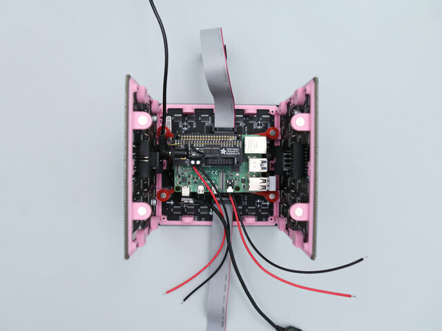
Insert the wires from the power cable through the bottom of the Pi mount. Reference image for correct placement.
Fit Pi Mount onto Panel #5
Attach Panel #3 and Panel #1 to Panel #5.
Place Pi mount over the tabs with magnets setting flush together.
Ensure USB cables and power wires are connected to the Raspberry Pi.
Connect Panel #5 to RGB Matrix Bonnet
Plug in the input data cable from Panel #5 to the HUB75 port on the RGB Matrix Bonnet.
Panel #4 Install
Place Panel #4 with edges "B" matching panel #5.
Connect the power cable to Panel #4.
Plug in the data output cable from Panel #5 to the data input on Panel #4.
Connect another data cable to the panels output port.
Panel #3 Install
Carefully separate Panel #3 from Panel #5 and lay it down on your work surface.
Connect a power cable to Panel #3.
Plug in the data output cable from Panel #4 to the data input on Panel #3.
Connect another data cable to the panels output port.
Attach Panel #3 to Panel #5 once again.
Panel #2 Install
Place Panel #2 down next to Panel #5 and match edges "C".
Connect a power cable to Panel #2.
Plug in the data output cable from Panel #3 to the data input on Panel #2.
Connect another data cable to the panels output port.
Attach Panel #2 to Panel #5 when ready.
Panel #1 Install
Carefully separate Panel #1 from Panel #5 and lay it down.
Connect a power cable to Panel #1.
Plug in data output cable from Panel #2 to the data input on Panel #1.
Connect another data cable to the panels output port.
Attach Panel #1 to Panel #5 once again.
Panel #1 Cube Fit
Ensure power and data cables are not being pinched when attaching Panel #1 back onto the panel assembly.
Panel #0 Install
Orient the cube assembly with Panel #1 laying down flat on your work surface.
Place Panel #0 down next to panel #1 and match edges "L".
Connect a power cable to Panel #0.
Plug in the data output from Panel #1 to the data input on Panel #0.
VCC Bus
Install all of the red wires from the power cables to the power distribution bus.
Use a screw driver to secure to the cables to the power distribution bus.
GND Bus
Install all of the black wires from the power cables to another power distribution bus.
Use a screw driver to secure to the cables to the power distribution bus.
Install Buses to Cube
Carefully fit the two power distribution buses into the cube assembly.
Adjust wire placement by neatly tucking in access wiring into the cube assembly.
Connect Battery
Plug in the USB-C cable from the Raspberry Pi into the 5V 3A USB Battery first.
Wait a few moments for the Pi to boot.
Then, plug in the USB cable from the RGB Matrix bonnet into the second USB port on the battery.
Install Battery
Carefully fit the battery into the cube assembly.
Adjust wiring to better fit the USB battery.
Final Cube Assembly
Carefully handle the cube assembly and orient Panel #0 with edges "J" matching. Remaining edges should be matching.
Attach Panel #0 with the rest of the cube assembly.
Congratulations on your build!!


