Insert the Cobbler into the center of the perma-proto board and solder all pins in place. Connect 5v to one power rail of the board, and 3v to the other, as shown. (To remind myself of the different voltage rails, I marked the 3v wire with a piece of white heat shrink.) Connect ground to both ground rails.
|
|


Connect the Thermal Printer
Cut the cables for the thermal printer in half, we will only use one half for each bundle - for the red and black bundle make sure you are working with the end that fits into the printer. We won't be using the green TX wire, so trim it to about an inch and attach it to the other wires with heat shrink to keep it out of the way.

|
|
|


Connect the cut ends of the wires to the Cobbler on the perma-proto board: Yellow to TXD, black to GND. Set the power and ground wires aside for now.

Connect the Accelerometer
Prepare the accelerometer by soldering wires about 6" long to VIN, GND, SDA, and SCL. Connect the wires to the perma-proto Board according to the circuit diagram: VIN goes to the 3v rail, GND to the GND rail, SDA to GPIO 2 (SDA), and SCL to GPIO 3 (SLC).


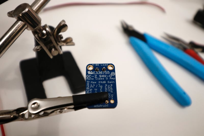
Connect the Amplifier
Prepare the amplifier: Insert the included screw terminals into power and ground and solder on the back of the board to attach. Solder 6" long wires to VIN and GND. Connect the wires to the perma-proto Board: VIN to the 5v rail, and GND to the GND rail.

|
|

Add Connectors to the Button Wires
Locate the button wires coming from the front panel. In case we need to take SelfieBot apart in the future, we'll add connectors to these wires so that they can come apart. There are four wires coming from the button, so a 4-pin connector like this is perfect. (I had a bunch of two-pin connectors on hand, so I used them.) Solder the connectors to the button wires, and to the perma-proto board: both black wires to GND, red to 5v, and white to GPIO 17 on the Cobbler.
My connectors came pre-wired with black and red wire, so I soldered them to the wires as shown, and covered the solder points with heat-shrink. Since my white data wire connected to a red wire on the connector, I marked it near the connector with a piece of white heat shrink.
|
|
|
|
|


The perma-proto board is complete! That's most of the wiring done, and if you want to change or add anything in the future, there's still plenty of room on the board for modifications. Now's a great time to take a break, and then move on to the power circuit!


