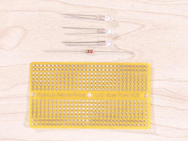

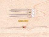
Prepping LEDs
Let's start off by getting our parts together for wiring our LEDs. In this project, I used a piece of flexible PCB, a 220ohm resistor and 3x 3mm LEDs.

Ground Wires
We'll need some wires to connect our LEDs together. Here, I'm using 30AWG silicone coated stranded wire. I'll started with making four pieces of wire for our ground connections. Three of these pieces are 10cm in length. The four, is shorter and a bit longer than the piece of flex PCB.


Tinning Wires
Next, remove 2-3mm of insulation from the tips of each wire. Then, apply some solder to the tips to tin them. This will prevent the stranded wire from fraying and makes it easier to solder to LEDs and the GPIO.
Pro Tip: Use a helping third hand to hold multiple wires to tin more than one wire at a time.


LED Ground Wire
Trim the short leg from the LED - This is the ground (cathode). Then, apply some solder to it and connect one of the three long wires by soldering it in place.


Prep Signal Wires
Next up, let's prep our wires for the signal connections. You only need 3 wires, this can be different colors to help tell them apart. Same length (10cm) just like the ground wires.


Wire Signal
Just like we did for the ground (cathode), trim the power (annode) legs from the LED and apply solder to tin. Then, connect one of the singal wires to it.


Installing LEDs
We can now install the LEDs into the 3D printed antenna part. Insert the ground and signal wires from one of the LEDs into one of the holes in the part. Thread it through and pull the wire until the head of LED is touching the atenna part. It should have a snug fit.


Connecting Ground Wires
Now it's time to connect our ground wires together. Start by tinning the holes on the flexible PCB. This will help connect the ground wires to them easier. Then, solder each wire into a pad on the flexible PCB.

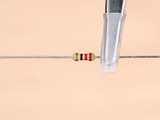

Wiring Resistor
We'll need to connect a resistor to avoid burning out the LEDs. Cut one of the legs from the resistor short and solder on the short ground wire by tinning.


Connecting Resistor
Insert the remaining leg from the resistor into the last hole on the flexible PCB. Then, solder the leg in place. Flip the flexible PCB over and solder the other ground wires to the leg - this will make the flexible PCB strong and less likely to break. After that, you can trim the excess leg from the resistor.

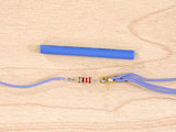

Heatshrink Connections
We'll need to insulate to exposd resistor and flex PCB so it doesn't short anything out when we install it on the Pi. We can do this by using a piece of heat shrink tubing (or electrical tape). Slip the piece over the short ground wire and heat it up to tighten the tubing.


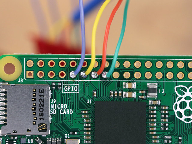
Connect LEDs to GPIO
Now it's time to solder the signal wires from the LEDs to the GPIO pins on the Raspberry Pi. You'll want to take note of which wire is connected to which LED on the antenna part. Below, I've listed out the LEDs, wire color, GPIO and pin number.
- Ground - Blue Wire - Pin #9
- Tallest LED - Green Wire - GPIO 22 (Pin #11)
- Middle LED - Red Wire - GPIO 27 (Pin #13)
- Short LED - Yellow Wire - GPIO 17 (Pin #15)


