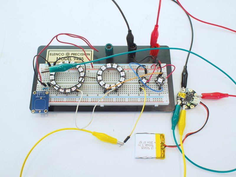
No fairy costume is complete without a glowing pixie dust bag. This one uses a touch sensor to cycle through colors on the beautifully twinkling NeoPixel rings, all powered by a tiny GEMMA microcontroller. This sophisticated-looking, rechargeable prop is easy to build with just a little bit of soldering.

This guide was written for the 'original' Gemma board, but can be done with either the original or M0 Gemma. We recommend the Gemma M0 as it is easier to use and is more compatible with modern computers!

You'll need:

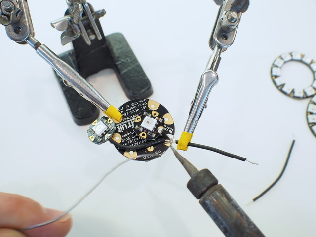
  • Gemma M0 or Original Gemma (M0 type is recommended!) - can also substitute Trinket M0 or Trinket Mini
  • RGB NeoPixel LEDs - two Flora pixels, one 12 x ring, and one 16 x ring
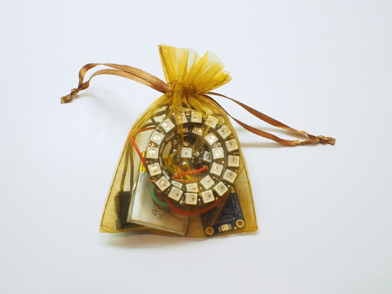
  • Small translucent fabric pouch
  • Scale model scenic snow in small plastic bag to diffuse pixels (or tissue paper, styrofoam beads, or another diffuser)
  • 500mAh rechargeable lipoly battery and charger
  • Tactile on/off switch
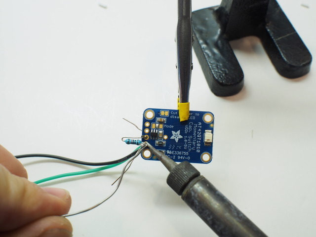
  • Momentary capacative touch sensor
  • 10k Ω resistor
  • Heat shrink tubing or electrical tape
  • Soldering iron and solder
  • Solid core or stranded wire (20 to 26 gauge)
  • Helping third hand tool
  • Wire strippers
  • Flush diagonal cutters
  • Solderless breadboard, hookup wire, and alligator clips for prototyping
  • Double-sided foam tape
  • Needle and thread
This diagram uses the original Gemma but you can also use the Gemma M0 with the exact same wiring!

The battery will be wired through a tactile switch to power the circuit on and off.

Power, ground, and control signals are wired from the GEMMA to the first FLORA pixel, then to the second, to the 12 LED ring, and finally to the 16 LED ring.

The momentary capacitive switch is wired as a pull-up resistor switch to ground and to the D2 pin of the GEMMA to read "button" pushes, and cycle through color choices.


This step is not optional! Avoid heartbreak later by testing your circuit now.

Use a breadboard, hook-up wire, and alligator clip leads to test out the circuit. This is a good way to get familiar with the connections you'll be making before soldering, as well as a chance to upload the sketch and test out the lighting effects.

If this is your first time using GEMMA, work through the Introducing GEMMA guide first; you need to customize some settings in the Arduino IDE (or download ours). Once you have it up and running (test the 'blink' sketch), then download and install the NeoPixel library:

Installing Arduino libraries is a frequent stumbling block. If this is your first time, or simply needing a refresher, please read the All About Arduino Libraries tutorial.If the library is correctly installed (and the Arduino IDE is restarted), you should be able to navigate through the “File” rollover menus as follows:

File→Sketchbook→Libraries→Adafruit_NeoPixel→strandtest

Connect up your NeoPixels in a solderless breadboard and use alligator clips to attach to GEMMA, referring to the circuit diagram if necessary.

You’ll need to change a few lines in the code regarding the data pin (1), and number of pixels (30). The resulting (and slightly simplified) code is below:

// SPDX-FileCopyrightText: 2017 John Edgar Park for Adafruit Industries
//
// SPDX-License-Identifier: MIT

//  NeoPixie Dust Bag by John Edgar Park jpixl.net
//   
//     No fairy costume is complete without a glowing pixie dust bag. 
//     This one uses a touch sensor to cycle through colors on the beautifully twinkling NeoPixel rings, 
//     controlled by the tiny Adafruit GEMMA microcontroller.
//
//     Build instructions: learn.adafruit.com/neopixel-pixie-dust-bag/overview
//
//  Some code based upon Adafruit GEMMA earring code and Adafruit NeoPixel buttoncycler code

#include <Adafruit_NeoPixel.h>  //Include the NeoPixel library

#define NEO_PIN 0        // DIGITAL IO pin for NeoPixel OUTPUT from GEMMA
#define TOUCH_PIN 2      // DIGITAL IO pin for momentary touch sensor INPUT to GEMMA
#define PIXEL_COUNT 30   // Number of NeoPixels connected to GEMMA
#define DELAY_MILLIS 10  // delay between blinks, smaller numbers are faster 
#define DELAY_MULT 8     // Randomization multiplier on the delay speed of the effect
#define BRIGHT 100        // Brightness of the pixels, max is 255

// Parameter 1 = number of pixels in strip
// Parameter 2 = pin number on Arduino (most are valid)
// Parameter 3 = pixel type flags, add together as needed:
//   NEO_RGB     Pixels are wired for RGB bitstream (v1 FLORA pixels, not v2)
//   NEO_GRB     Pixels are wired for GRB bitstream, correct for neopixel stick (most NeoPixel products)
//   NEO_KHZ400  400 KHz bitstream (e.g. FLORA pixels)
//   NEO_KHZ800  800 KHz bitstream (e.g. High Density LED strip), correct for neopixel stick
Adafruit_NeoPixel pixels = Adafruit_NeoPixel(PIXEL_COUNT, NEO_PIN, NEO_GRB + NEO_KHZ800);

bool oldState = HIGH; //sets the initial variable for counting touch sensor button pushes
int showColor = 0;    //color mode for cycling

void setup() {
  pinMode(TOUCH_PIN, INPUT);    //Initialize touch sensor pin as input using external pull-up resistor
  pixels.begin();
  pixels.setBrightness(BRIGHT);
  pixels.show();                //Set all pixels to "off"
}


void loop() {
  int RColor = 100; //color (0-255) values to be set by cylcing touch switch, initially GOLD
  int GColor = 0 ;
  int BColor = 0 ;
  
       if (showColor==0) {//Garden PINK
         RColor = 242;
         GColor = 90;
         BColor = 255; 
       }
       if (showColor==1) {//Pixie GOLD
         RColor = 255;
         GColor = 222;
         BColor = 30; 
       }
       if (showColor==2) {//Alchemy BLUE
         RColor = 50;
         GColor = 255;
         BColor = 255; 
       }
       if (showColor==3) {//Animal ORANGE
         RColor = 255;
         GColor = 100;
         BColor = 0; 
       }
       if (showColor==4) {//Tinker GREEN
         RColor = 0;
         GColor = 255;
         BColor = 40; 
       }
  
  //sparkling
  int p = random(PIXEL_COUNT); //select a random pixel
  pixels.setPixelColor(p,RColor,GColor,BColor); //color value comes from cycling state of momentary switch
  pixels.show();
  delay(DELAY_MILLIS * random(DELAY_MULT) ); //delay value randomized to up to DELAY_MULT times longer
  pixels.setPixelColor(p, RColor/10, GColor/10, BColor/10); //set to a dimmed version of the state color
  pixels.show();
  pixels.setPixelColor(p+1, RColor/15, GColor/15, BColor/15); //set a neighbor pixel to an even dimmer value
  pixels.show();
  
  //button check to cycle through color value sets
  bool newState = digitalRead(TOUCH_PIN); //Get the current button state
  // Check if state changed from high to low (button press).
  if (newState == LOW && oldState == HIGH) {
    // Short delay to debounce button.
    delay(20);
    // Check if button is still low after debounce.
    newState = digitalRead(TOUCH_PIN);
    if (newState == LOW) {
      showColor++;
      if (showColor > 4)
        showColor=0;
       }   
  }
  // Set the last button state to the old state.
  oldState = newState;  
  
}

From the Tools→Board menu, select Adafruit Gemma 8MHzor Adafruit Trinket 8 MHz as appropriate. Connect the USB cable between the computer and GEMMA, press the reset button on the board, then click the upload button (right arrow icon) in the Arduino IDE. When the battery is connected, you should get a light show from the LEDs. All your pixels working? Great! You can take apart this prototype and get ready to put the pixels in the collar. Refer to the NeoPixel Uberguide for more info.

The Arduino code presented below works equally well on all versions of GEMMA: v1, v2 and M0. But if you have an M0 board, consider using the CircuitPython code on the next page of this guide, no Arduino IDE required!

With the circuit prototyped and the GEMMA connected to your computer, it's time to upload the NeoPixie Dust Bag sketch. This program randomly twinkles the NeoPixels and changes color each time you touch the capsense switch.

Click the "Copy Code" link at the top of the code block, then create a new sketch in the Adafruit Arduino IDE by clicking File > New. Then, paste the code by clicking Edit > Paste in the Arduino menu. Upload the code to your GEMMA by pressing the reset button on the GEMMA, waiting for the onboard red LED to blink, and then clicking File > Upload in the Arduino IDE.

Once the code has been uploaded, your NeoPixie Dust Bag will begin to twinkle in the traditional, golden pixie dust hue. Tap the capsense switch to change it to blue. Be amazed and overjoyed! Then, keep trying out the different color shifts, or, modify the code to create your own colors.

// SPDX-FileCopyrightText: 2017 John Edgar Park for Adafruit Industries
//
// SPDX-License-Identifier: MIT

//  NeoPixie Dust Bag by John Edgar Park jpixl.net
//   
//     No fairy costume is complete without a glowing pixie dust bag. 
//     This one uses a touch sensor to cycle through colors on the beautifully twinkling NeoPixel rings, 
//     controlled by the tiny Adafruit GEMMA microcontroller.
//
//     Build instructions: learn.adafruit.com/neopixel-pixie-dust-bag/overview
//
//  Some code based upon Adafruit GEMMA earring code and Adafruit NeoPixel buttoncycler code

#include <Adafruit_NeoPixel.h>  //Include the NeoPixel library

#define NEO_PIN 0        // DIGITAL IO pin for NeoPixel OUTPUT from GEMMA
#define TOUCH_PIN 2      // DIGITAL IO pin for momentary touch sensor INPUT to GEMMA
#define PIXEL_COUNT 30   // Number of NeoPixels connected to GEMMA
#define DELAY_MILLIS 10  // delay between blinks, smaller numbers are faster 
#define DELAY_MULT 8     // Randomization multiplier on the delay speed of the effect
#define BRIGHT 100        // Brightness of the pixels, max is 255

// Parameter 1 = number of pixels in strip
// Parameter 2 = pin number on Arduino (most are valid)
// Parameter 3 = pixel type flags, add together as needed:
//   NEO_RGB     Pixels are wired for RGB bitstream (v1 FLORA pixels, not v2)
//   NEO_GRB     Pixels are wired for GRB bitstream, correct for neopixel stick (most NeoPixel products)
//   NEO_KHZ400  400 KHz bitstream (e.g. FLORA pixels)
//   NEO_KHZ800  800 KHz bitstream (e.g. High Density LED strip), correct for neopixel stick
Adafruit_NeoPixel pixels = Adafruit_NeoPixel(PIXEL_COUNT, NEO_PIN, NEO_GRB + NEO_KHZ800);

bool oldState = HIGH; //sets the initial variable for counting touch sensor button pushes
int showColor = 0;    //color mode for cycling

void setup() {
  pinMode(TOUCH_PIN, INPUT);    //Initialize touch sensor pin as input using external pull-up resistor
  pixels.begin();
  pixels.setBrightness(BRIGHT);
  pixels.show();                //Set all pixels to "off"
}


void loop() {
  int RColor = 100; //color (0-255) values to be set by cylcing touch switch, initially GOLD
  int GColor = 0 ;
  int BColor = 0 ;
  
       if (showColor==0) {//Garden PINK
         RColor = 242;
         GColor = 90;
         BColor = 255; 
       }
       if (showColor==1) {//Pixie GOLD
         RColor = 255;
         GColor = 222;
         BColor = 30; 
       }
       if (showColor==2) {//Alchemy BLUE
         RColor = 50;
         GColor = 255;
         BColor = 255; 
       }
       if (showColor==3) {//Animal ORANGE
         RColor = 255;
         GColor = 100;
         BColor = 0; 
       }
       if (showColor==4) {//Tinker GREEN
         RColor = 0;
         GColor = 255;
         BColor = 40; 
       }
  
  //sparkling
  int p = random(PIXEL_COUNT); //select a random pixel
  pixels.setPixelColor(p,RColor,GColor,BColor); //color value comes from cycling state of momentary switch
  pixels.show();
  delay(DELAY_MILLIS * random(DELAY_MULT) ); //delay value randomized to up to DELAY_MULT times longer
  pixels.setPixelColor(p, RColor/10, GColor/10, BColor/10); //set to a dimmed version of the state color
  pixels.show();
  pixels.setPixelColor(p+1, RColor/15, GColor/15, BColor/15); //set a neighbor pixel to an even dimmer value
  pixels.show();
  
  //button check to cycle through color value sets
  bool newState = digitalRead(TOUCH_PIN); //Get the current button state
  // Check if state changed from high to low (button press).
  if (newState == LOW && oldState == HIGH) {
    // Short delay to debounce button.
    delay(20);
    // Check if button is still low after debounce.
    newState = digitalRead(TOUCH_PIN);
    if (newState == LOW) {
      showColor++;
      if (showColor > 4)
        showColor=0;
       }   
  }
  // Set the last button state to the old state.
  oldState = newState;  
  
}
Keep your body parts away from the capacitive switch when the circuit is turning on so it can calibrate itself.

GEMMA M0 boards can run CircuitPython — a different approach to programming compared to Arduino sketches. In fact, CircuitPython comes factory pre-loaded on GEMMA M0. If you’ve overwritten it with an Arduino sketch, or just want to learn the basics of setting up and using CircuitPython, this is explained in the Adafruit GEMMA M0 guide.

These directions are specific to the “M0” GEMMA board. The original GEMMA with an 8-bit AVR microcontroller doesn’t run CircuitPython…for those boards, use the Arduino sketch on the “Arduino code” page of this guide.

Below is CircuitPython code that works similarly (though not exactly the same) as the Arduino sketch shown on a prior page. To use this, plug the GEMMA M0 into USB…it should show up on your computer as a small flash drive…then edit the file “code.py” with your text editor of choice. Select and copy the code below and paste it into that file, entirely replacing its contents (don’t mix it in with lingering bits of old code). When you save the file, the code should start running almost immediately (if not, see notes at the bottom of this page).

If GEMMA M0 doesn’t show up as a drive, follow the GEMMA M0 guide link above to prepare the board for CircuitPython.

# SPDX-FileCopyrightText: 2017 Mikey Sklar for Adafruit Industries
#
# SPDX-License-Identifier: MIT

# NeoPixie Dust Bag
# learn.adafruit.com/neopixel-pixie-dust-bag

import time

import board
import digitalio
import neopixel

try:
    import urandom as random  # for v1.0 API support
except ImportError:
    import random

neo_pin = board.D0  # DIGITAL IO pin for NeoPixel OUTPUT from GEMMA
touch_pin = board.D2  # DIGITAL IO pin for momentary touch sensor to GEMMA
pixel_count = 30  # Number of NeoPixels connected to GEMMA
delay_sec = .010  # delay between blinks, smaller numbers are faster
delay_mult = 8  # Randomization multiplier, delay speed of the effect

# initialize neopixels
pixels = neopixel.NeoPixel(
    neo_pin, pixel_count, brightness=.4, auto_write=False)

oldstate = False  # counting touch sensor button pushes
showcolor = 0  # color mode for cycling

# initialize external capacitive touch pad (active high)
button = digitalio.DigitalInOut(touch_pin)
button.direction = digitalio.Direction.INPUT
button.pull = digitalio.Pull.UP

while True:

    rcolor = 100  # swtich cycles colors, initially GOLD
    gcolor = 0
    bcolor = 0

    if showcolor == 0:  # Garden PINK
        rcolor = 242
        gcolor = 90
        bcolor = 255

    elif showcolor == 1:  # Pixie GOLD
        rcolor = 255
        gcolor = 222
        bcolor = 30

    elif showcolor == 2:  # Alchemy BLUE
        rcolor = 50
        gcolor = 255
        bcolor = 255

    elif showcolor == 3:  # Animal ORANGE
        rcolor = 255
        gcolor = 100
        bcolor = 0

    elif showcolor == 4:  # Tinker GREEN
        rcolor = 0
        gcolor = 255
        bcolor = 40

    # sparkling
    # select a random pixel
    p = random.randint(0, (pixel_count - 2))
    # color value from momentary switch
    pixels[p] = (rcolor, gcolor, bcolor)
    pixels.write()

    # delay value randomized to up to delay_mult times longer
    time.sleep(delay_sec * random.randint(0, delay_mult))

    # set to a dimmed version of the state color
    pixels[p] = (int(rcolor / 10), int(gcolor / 10), int(bcolor / 10))
    pixels.write()

    # set a neighbor pixel to an even dimmer value
    pixels[p + 1] = (int(rcolor / 15), int(gcolor / 15), int(bcolor / 15))
    pixels.write()

    # button check to cycle through color value sets
    # get the current button state
    newstate = button.value

    # Check if state changed from low to high (button/touchpad press).
    if newstate and not oldstate:
        # cycle to next color
        showcolor += 1

        # limit the cycle to the 5 colors
        if showcolor > 4:
            showcolor = 0

        # give feedback to the REPL to debug the touch pad
        # print("Color:", showcolor)

    # Set the last button state to the old state.
    oldstate = newstate

This code requires the neopixel.py library. A factory-fresh board will have this already installed. If you’ve just reloaded the board with CircuitPython, create the “lib” directory and then download neopixel.py from Github.

Before wiring and soldering things togeter, it's a good idea to fit all of the parts together to get an idea of the physical layout, how it will all fit in the bag, and how the switches will be accessed and how the battery will be recharged.

Place the GEMMA "face down" (the word GEMMA and Adafruit logo should be facing up, and then set the two Flora pixels, 12 x ring, and 16 x ring on top of it. This will allow you to access the reset button, battery port, and USB port once assembled.


Cut and strip short lengths of wire to connect the GEMMA to the first Flora NeoPixel. You can follow the Circuit Diagram image for wire color.

To wire them, pass the stripped ends of the wires through the holes on the NeoPixels and the GEMMA, solder them, and then  snip the excess wire ends with the diagonal cutters.


It helps to use a third-hand tool to hold the components during soldering. Also, be sure to solder in a well-ventilated area, preferably with a soldering exhaust fan. 

You will need to solder multiple wires to a single pad in some cases -- for example, there are six connections to the GROUND pad of the GEMMA.


You won't be able to fit all six wires through the through-hole, in this case it's fine to solder directly to the copper pad. Use both sides of the board if you run out of room to solder on one side.

Solder the data connection between the two Flora pixels (the blue wire in the circuit diagram) by lining up the out pin → of the first Flora with the ← in pin of the second Flora, inserting a small length of wire, and then soldering them together.

Continue soldering the remaining data, power, and ground connections to all of the NeoPixels.

Continue soldering the remaining data, power, and ground connections to all of the NeoPixels.

Next, you'll wire up the momentary capacative touch sensor breakout board. Bend the leads of the 10K Ohm resistor and insert them into the capsense board's OUT and GND connections.

Cover the bent resistor in a small piece of heat shrink tubing and heat it with the side of your soldering iron to insulate the connection. If you don't want the on-board red LED to light up when you touch the sensor, cut the trace on the board as directed here.

Solder the wires and resistor leads to the board. This will create the circuit of the pull-up resitor, as well as provide power to the board. Cut off the excess wire strands and resistor leads.

Plug the battery into the GEMMA to test the capsense board. It has an on-board LED which will light up when you touch the board. 

Cover the bent resistor in a small piece of heat shrink tubing and heat it with the side of your soldering iron to insulate the connection.


If you don't want the on-board red LED to light up when you touch the sensor, cut the trace on the board as directed here.

You'll splice the tactile switch into the battery's ground wire in order to turn the circuit on and off. Unplug the battery from the GEMMA before this step. Cut the battery's black wire in half with diagonal cutters, and then strip the ends.


Trim the tactile switch wires down to 2" in length, and then strip the ends. Place a 1/2" length of heat shrink tubing on each of the tactile switch leads. Twist one switch lead to each of the black battery wires, then solder them each.


Slide the heat shrink tubing over the bare connections and heat the tubing with the side of your soldering iron (or use electrician's tape) in order to insulate the connections.

Plug the battery JST connector into the GEMMA and test the tactile switch. It should turn the circuit on and off.

Once on, test out the capacitive sense switch to cycle through the different LED colors.

Dry fit all of the parts into the drawstring bag to get an idea of where things will best fit.  This is a good time to double-check that everything still works, particularly the capsense switch through the fabric.

Use a small piece of double stick foam tape to affix the tactile switch to the battery.

With additional piece of double stick foam tape, connect the two Flora pixels to the GEMMA board, and the rings to the Flora pixels and each other.

Place the capsense switch inside the bag where you'll be able to touch it, then use a needle and thread to stitch its two bottom corners to the side of the bag that the sensor is facing. Don't go through both layers of the bag.

Place the battery/switch combination in the other bottom corner of the bag, then insert the GEMMA/NeoPixel assembly.

Fill a small plastic bag with the scale model snow (or styrofoam beads, rice, or another diffusing material of your choice).


Then place the plastic diffuser bag in the pixie dust bag, in front of the GEMMA/NeoPixel assembly.

Pull the drawstring on your bag tight, and press the tactile switch to turn on the magic of the pixie dust!

Tap the capsense switch to try out the different beautiful colors. The bag will look especially wonderful in the dark!

Enjoy spreading your pixie dust magic. Should your power run out, simply disconnect the battery JST switch from the GEMMA, and plug it in to the charger, which you'll in turn plug into a USB port. Once the battery is charged, reconnect it to your GEMMA.

This guide was first published on Oct 22, 2014. It was last updated on Apr 16, 2024.