When you think of the word turntable, you might think of something that you play a record on, but for this project, at least, we're going to build a different type of turntable. A turntable, in the video and photography world, is a flat platform on a stand that spins around, allowing you to get a 360 degree view of an object. This is great for adding movement to video, focusing on details that you otherwise might miss, and to raise an object up for better lighting. Turntables, much like other pieces of production equipment, can carry a premium price tag with minimum features.

For this project, we'll go over how to build your own turntable with the ability to have adjustable rotation speed, rotate both clockwise and counterclockwise, and 3D print interchangeable platforms.

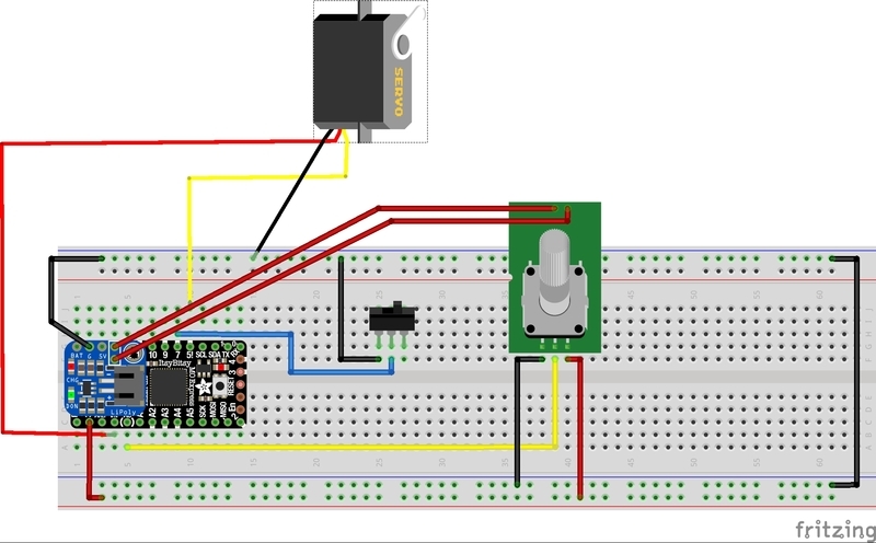
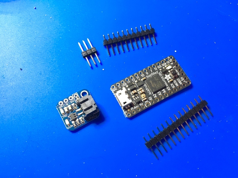
For supplies you'll need:

The circuit for this project is fairly simple, using only five main components including the Itsy Bitsy board. The Itsy Bitsy M0 is running CircuitPython code to control everything and to supply power and ground via USB or battery power. A LiPo backpack is soldered on top of the Itsy Bitsy to easily add-in a LiPo battery for power that can be charged via the Itsy Bitsy's USB port and to allow for a power switch.

A potentiometer with a built-in switch controls the rotation speed and can turn everything on or off. A SPDT switch controls whether the turntable spins clockwise or counterclockwise and of course, the star of the show, a servo motor, of the continuously rotating variety, receives its orders from the components while sporting a circular horn that will fit into its 3D printed part.

Running on an Itsy Bitsy M0 means that we can code this project with CircuitPython!

Are you new to using CircuitPython? No worries, there is a full getting started guide here.

Adafruit suggests using the Mu editor to edit your code and have an interactive REPL in CircuitPython. You can learn about Mu and installation in this tutorial.

We're using the adafruit_motor library for CircuitPython to easily control the servo by declaring the pin as a continuous servo motor.

You can learn about installing the adafruit_motor library in the CircuitPython Essentials Guide on CircuitPlayground Libraries. It is easiest to install the whole library package.

The code is listed below and is available on Adafruit's GitHub repository.

# SPDX-FileCopyrightText: 2018 Anne Barela for Adafruit Industries
#
# SPDX-License-Identifier: MIT

import time

import adafruit_motor.servo
import board
import pwmio
from analogio import AnalogIn
from digitalio import DigitalInOut, Direction, Pull

pwm = pwmio.PWMOut(board.D5, frequency=50)
servo = adafruit_motor.servo.Servo(pwm)
switch = DigitalInOut(board.D7)
switch.direction = Direction.INPUT
switch.pull = Pull.UP
pot = AnalogIn(board.A0)

continuous = adafruit_motor.servo.ContinuousServo(pwm)


def val(pin):
    # divides voltage (65535) to get a value between 0 and 1
    return pin.value / 65535


while True:

    if switch.value:
        continuous.throttle = val(pot) * -1
    else:
        continuous.throttle = val(pot) * 1

    time.sleep(0.001)

The potentiometer is going to read a minimum value of 0 and a maximum value of 1 because the servo's speed will range between 0 for no movement and 1 for maximum speed.

Additionally, for the continuous rotation servo, a maximum value of 1 means the maximum speed for clockwise motion and -1 means the maximum speed for counterclockwise motion. This comes into play in the loop, where the switch begins to play a role. For the loop, whether or not the switch is HIGH will determine whether the servo is rotating clockwise or counterclockwise by multiplying the speed registered by the potentiometer by either 1 or -1.

There are two 3D printed parts for the turntable: the electronics enclosure/base and the turntable platform. The enclosure has a snap fit back to easily access the electronics. I followed along with the Ruiz Brothers' tutorial for snap fit enclosures that you can find on YouTube here:

The enclosure also has cutouts for the USB micro B extension to poke out the side and a spot for the servo to stick out of the top. Holes are in the front for the potentiometer and switch. The hole for the switch also has arrows above it to denote that it's switching directions.

The entire design is parametric, so you can adjust it to (literally) fit your needs, whether you need a larger slot for a motor or want the enclosure to be bigger or smaller. You can download both the Fusion360 file below or the .STL file from Thingiverse.

For printing, I printed it at .2 layer height and 20% infill. You do need some supports because of the USB and servo cutouts, but if you're feeling brave you can certainly try it with no supports.

The turntable platform is also designed to be parametric and is available in the same Fusion360 file. The base fits perfectly around the circular disc that comes as an option with the servo motor. The point of this design is that you can print multiple platforms in different filaments, or even different shapes and sizes, to fit different needs you may have for various b-roll and photography situations.

Now the fun part, putting everything together. First up is soldering the electronics. I used a quarter-sized perma proto board to have all the electronics live on like a tiny breadboard island. The quarter-sized variation is the perfect size for an Itsy Bitsy with about one row to spare.

In order to have the option to remove the Itsy Bitsy easily later, start with two rows of female headers spaced so that the Itsy Bitsy will be able to slot in. Next you'll solder the male headers to the Itsy Bitsy board along with the three longer headers that the lipo backpack will be soldered to.

Before soldering the lipo backpack to the Itsy Bitsy, solder two pieces of wire to the solder points on the board for a power button. These will be attached to the switch terminals on the potentiometer. After that, cut the trace that is between the two holes. This allows an on/off switch to work. Use a hobby knife or other similar tool to cut this. Once that step is complete, you can solder the lipo backpack to the Itsy Bitsy.

Always be careful when using a knife to cut something!

Up next is the wiring for the components according to the circuit diagram from the Electronics portion of the guide. Wires for ground, power and data for the servo are left exposed on one end so that they can plug into the servo's included header.

After soldering, you can put the electronics into the enclosure. Start by running the USB micro B extension into the side hole and securing it with its screws. Next, take the other end of the extension and plug it into the Itsy Bitsy board by running it under the board between the headers to save room inside the enclosure.

3d_printing_edited_P1060648.jpg

3d_printing_edited_P1060649.jpg

3d_printing_edited_P1060650.jpg

Then take the switch and potentiometer and insert them into their respective holes at the front of the enclosure. Once they're thru, secure them with their included washers and nuts. After that, you can slide the electronics fully into the enclosure, leaving the three wires for the servo off to the side. Insert the servo into the top slot and then plug the three wires into the servo's header. Close-up the enclosure by snapping on the lid.

3d_printing_edited_P1060651.jpg

3d_printing_edited_P1060653.jpg

3d_printing_edited_P1060657.jpg

For finishing touches add a knob to the potentiometer and pop the circular horn onto the servo. Top the servo off with the turntable platform and your turntable is ready to spin off into the sunset.

This guide was first published on May 09, 2018. It was last updated on May 09, 2018.