

Prep Bonnet
First, we'll need to add a jumper to connect two pins and then bridge two pads to enable the RGB Matrix Bonnet to work with the 64x64 LED Matrix.
Jumper
We'll start by measuring a wire 30mm long. Tin and solder pin 4 to pin 18. Carefully bend the wire and move it away from the headers on the Bonnet.
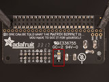
Bridge Pad
Next, we need to turn the Matrix Bonnet over and locate the three solder pads. Tin the middle pad "E" and the "8" pad. Now heat up one of the pads and drag solder over to the next pad to bridge the two connections.


Attach LED Matrix to Frame
Once 3D frame is printed and glued, use flat screws to connect the display. It is important to keep these flat, to it sits seamlessly over the headboard surface.
The ribbon cable goes next and in order to make the surface flat, I went ahead and removed the back side of the plastic shield that attaches the end cable to the display.
Carefully solder 5V and GND to display, so it is... you get the idea... FLAT!


Glue on!
With glue gun hot and ready, I bonded the RPI and ribbon cable to the back side of the frame. There are plenty of holes in the back plane, so you can attach the RPI to the frame.
The cover provided as the 3rd STL file will fit nicely over the RPI, so this part is not exposed.


Solder APDS9960
The Proximity, Light, RGB, and Gesture Sensor is soldered to the Bonnet. Measure four wires long enough to connect 5v, GND, SDA, and SLC on the Bonnet and APDS9960 .


Hang overboard
And that is it, folks! For more pictures on this assembly, take a look at this link.
You might consider a stand instead for nightstand use.
Check out this video to see the bedclock in action


