Using the MLX90393 with CircuitPython is easy. The Adafruit_CircuitPython_MLX90393 repo on Github always contains the latest public code, and allows you to quickly and easily get started with the Adafruit MLX90393 breakout board.
CircuitPython Wiring
The diagram below shows how you can wire up your CircuitPython board (in Feather form below) to the MLX90393:
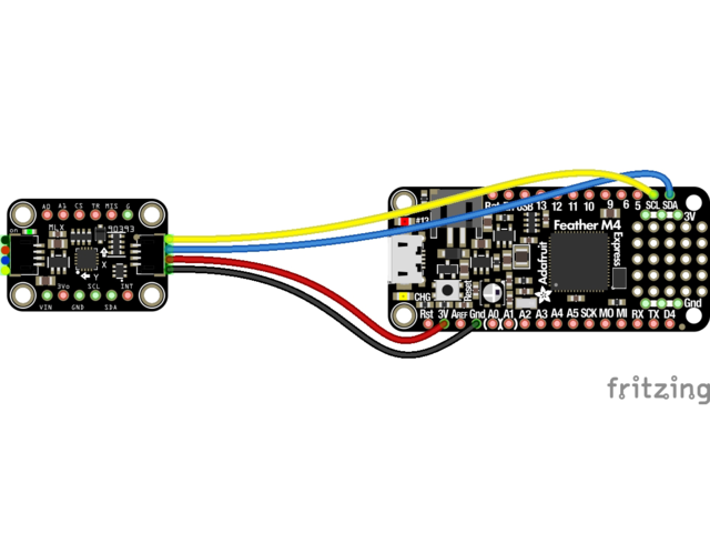


Simple connect:
- 3V on the dev board to VIN on the MLX90393 (red wire on STEMMA QT version)
- GND on the dev board to GND on the MLX90393 (black wire on STEMMA QT version)
- SCL on the dev board to SCL on the MLX90393 (yellow wire on STEMMA QT version)
- SDA on the dev board to SDA on the MLX90393 (blue wire on STEMMA QT version)
Python Wiring
Since there's dozens of Linux computers/boards you can use we will show wiring for Raspberry Pi. For other platforms, please visit the guide for CircuitPython on Linux to see whether your platform is supported.
Make the following connections between the Pi and the MLX90393:


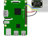

Simple connect:
- 3.3V on the RPi to VIN on the MLX90393 (red wire on STEMMA QT version)
- GND on the RPi to GND on the MLX90393 (black wire on STEMMA QT version)
- SCL on the RPi to SCL on the MLX90393 (yellow wire on STEMMA QT version)
- SDA on the RPi to SDA on the MLX90393 (blue wire on STEMMA QT version)
Library Installation
You'll need to install the Adafruit CircuitPython MLX90393 library on your CircuitPython board.
First make sure you are running the latest version of Adafruit CircuitPython for your board.
Next you'll need to install the necessary libraries to use the hardware--carefully follow the steps to find and install these libraries from Adafruit's CircuitPython library bundle. Our CircuitPython starter guide has a great page on how to install the library bundle.
For non-express boards like the Trinket M0 or Gemma M0, you'll need to manually install the necessary libraries from the bundle:
- adafruit_mlx90393.mpy
- adafruit_bus_device
Before continuing make sure your board's lib folder or root filesystem has the adafruit_mlx90393.mpy, and adafruit_bus_device files and folders copied over.
Next connect to the board's serial REPL so you are at the CircuitPython >>> prompt.
Python Installation of the MLX90393 Library
You'll need to install the Adafruit_Blinka library that provides the CircuitPython support in Python. This may also require enabling I2C on your platform and verifying you are running Python 3. Since each platform is a little different, and Linux changes often, please visit the CircuitPython on Linux guide to get your computer ready!
Once that's done, from your command line run the following command:
sudo pip3 install adafruit-circuitpython-mlx90393
If your default Python is version 3 you may need to run 'pip' instead. Just make sure you aren't trying to use CircuitPython on Python 2.x, it isn't supported!
Example
The following example shows a minimal python script to make use of the MLX90393.
Running this example, a three axis magnetic field measurement will be read every second, and displayed via the serial output. A timestamp will precede each sample, and if any error condition was encountered during the read attempt, the details of the error code will be displayed:
# SPDX-FileCopyrightText: 2021 ladyada for Adafruit Industries
# SPDX-License-Identifier: MIT

import time
import board
import adafruit_mlx90393

i2c = board.I2C()  # uses board.SCL and board.SDA
# i2c = board.STEMMA_I2C()  # For using the built-in STEMMA QT connector on a microcontroller
SENSOR = adafruit_mlx90393.MLX90393(i2c, gain=adafruit_mlx90393.GAIN_1X)

while True:
    MX, MY, MZ = SENSOR.magnetic
    print("[{}]".format(time.monotonic()))
    print("X: {} uT".format(MX))
    print("Y: {} uT".format(MY))
    print("Z: {} uT".format(MZ))
    # Display the status field if an error occured, etc.
    if SENSOR.last_status > adafruit_mlx90393.STATUS_OK:
        SENSOR.display_status()
    time.sleep(1.0)
If you open the Serial tab in mu-editor with the sample code running, you should get output resembling the following if everything was setup correctly:

SENSOR.gain = adafruit_mlx90393.GAIN_2X
Alternatively, you can set the gain property via the constructor, as shown below:
SENSOR = adafruit_mlx90393.MLX90393(I2C_BUS, gain=adafruit_mlx90393.GAIN_1X)
The value assigned to the gain property can be one of the following entries:
- GAIN_5X
- GAIN_4X
- GAIN_3X
- GAIN_2_5X
- GAIN_2X
- GAIN_1_67X
- GAIN_1_33X
- GAIN_1X
Resolution is managed internally in the driver itself, and defaults to the maximum value of +/- 2^15 LSBs.


