Adafruit CircuitPython Module Install
To use the PCA9685 with your Adafruit CircuitPython board you'll need to install the Adafruit_CircuitPython_PCA9685 module on your board. Remember this module is for Adafruit CircuitPython firmware and not MicroPython.org firmware!
First make sure you are running the latest version of Adafruit CircuitPython for your board. Next you'll need to install the necessary libraries to use the hardware--read below and carefully follow the referenced steps to find and install these libraries from Adafruit's CircuitPython library bundle with a version 20180110 or newer.
Bundle Install
For express boards that have extra flash storage, like the Feather/Metro M0 express and Circuit Playground express, you can easily install the necessary libraries with Adafruit's CircuitPython bundle. This is an all-in-one package that includes the necessary libraries to use the PCA9685 with CircuitPython. To install the bundle follow the steps in your board's guide, like these steps for the Feather M0 express board.
Remember for non-express boards like the Trinket M0, Gemma M0, and Feather/Metro M0 basic you'll need to manually install the necessary libraries from the bundle:
- adafruit_pca9685
- adafruit_bus_device
- adafruit_register
- adafruit_motor
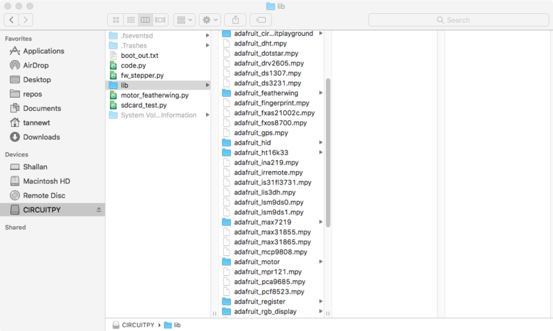
If your board supports USB mass storage, like the M0-based boards, then simply drag the files to the board's file system. Note on boards without external SPI flash, like a Feather M0 or Trinket/Gemma M0, you might run into issues on Mac OSX with hidden files taking up too much space when drag and drop copying, see this page for a workaround.
If your board doesn't support USB mass storage, like the ESP8266, then use a tool like ampy to copy the file to the board. You can use the latest version of ampy and its new directory copy command to easily move module directories to the board.
Before continuing make sure your board's lib folder or root filesystem has the adafruit_pca9685, adafruit_bus_device, adafruit_register and adafruit_motor folders/modules copied over.
Usage
The following section will show how to control the PCA9685 from the board's Python prompt / REPL. You'll learn how to interactively control servos and dim LEDs by typing in the code below.
First connect to the board's serial REPL so you are at the CircuitPython >>> prompt.
I2C Initialization
First you'll need to initialize the I2C bus for your board. First import the necessary modules:
import board
import busio
Now for either board run this command to create the I2C instance using the default SCL and SDA pins (which will be marked on the boards pins if using a Feather or similar Adafruit board):
i2c = busio.I2C(board.SCL, board.SDA)
After initializing the I2C interface you need to import the PCA9685 module to use it in your own code:
import adafruit_pca9685
Dimming LED's
Each channel of the PCA9685 can be used to control the brightness of an LED. The PCA9685 generates a high-speed PWM signal which turns the LED on and off very quickly. If the LED is turned on longer than turned off it will appear brighter to your eyes.
First wire a LED to the board as follows. Note you don't need to use a resistor to limit current through the LED as the PCA9685 will limit the current to around 10mA:

- LED cathode / shorter leg to PCA9685 channel GND / ground.
- LED anode / longer leg to PCA9685 channel PWM.
Now in the Python REPL you can create an instance of the basic PCA9685 class which provides low-level PWM control of the board's channels:
pca = adafruit_pca9685.PCA9685(i2c)
The PCA9685 class provides control of the PWM frequency and each channel's duty cycle. Check out the PCA9685 class documentation for more details.
For dimming LEDs you typically don't need to use a fast PWM signal frequency and can set the board's PWM frequency to 60hz by setting the frequency attribute:
pca.frequency = 60
The PCA9685 supports 16 separate channels that share a frequency but can have independent duty cycles. That way you could dim 16 LEDs separately!
The PCA9685 object has a channels attribute which has an object for each channel that can control the duty cycle. To get the individual channel use the [] to index into channels.
led_channel = pca.channels[0]
Now control the LED brightness by controlling the duty cycle of the channel connected to the LED. The duty cycle value should be a 16-bit value, i.e. 0 to 0xffff, which represents what percent of the time the signal is on vs. off. A value of 0xffff is 100% brightness, 0 is 0% brightness, and in-between values go from 0% to 100% brightness.
For example set the LED completely on with a duty cycle of 0xffff:
led_channel.duty_cycle = 0xffff
After running the command above you should see the LED light up at full brightness!
Now turn the LED off with a duty cycle of 0:
led_channel.duty_cycle = 0
Try an in-between value like 1000:
led_channel.duty_cycle = 1000
You should see the LED dimly lit. Try experimenting with other duty cycle values to see how the LED changes brightness!
For example make the LED glow on and off by setting duty_cycle in a loop:
# Increase brightness:
for i in range(0xffff):
    led_channel.duty_cycle = i

# Decrease brightness:
for i in range(0xffff, 0, -1):
    led_channel.duty_cycle = i
These for loops take a while because 16-bits is a lot of numbers. CTRL-C to stop the loop from running and return to the REPL.
Control Servos
Servo motors use a PWM signal to control the position of their arm or horn. Using the PCA9685 and the Motor library you can easily plug in servos and control them with Python. If you aren't familiar with servos be sure to first read this intro to servos page and this in-depth servo guide page.
First connect the servo to a channel on the PCA9685. Be sure to plug the servo connector in the correct way! Check your servo's datasheet to be sure, but typically the brown wire is connected to ground, the red wire is connected to 5V power, and the yellow pin is connected to PWM:

Be sure you've turned on or plugged in the external 5V power supply to the PCA9685 board too!
Now in the Python REPL as above with the led, save a variable for its channel:
servo_channel = pca.channels[0]
Servos typically operate at a frequency of 50 hz so update pca accordingly.
pca.frequency = 50
Now that the PCA9685 is set up for servos lets make a Servo object so that we can adjust the servo based on angle instead of duty_cycle.
By default the Servo class will use actuation range, minimum pulse-width, and maximum pulse-width values that should work for most servos. However check the Servo class documentation for more details on extra parameters to customize the signal generated for your servos.
import adafruit_motor.servo
servo = adafruit_motor.servo.Servo(servo_channel)
With Servo, you specify a position as an angle. The angle will always be between 0 and the actuation range given when Servo was created. The default is 180 degrees but your servo might have a smaller sweep--change the total angle by specifying the actuation_angle parameter in the Servo class initializer above.
Now set the angle to 180, one extreme of the range:
servo.angle = 180
Or to sweep back to the minimum 0 degree position:
servo.angle = 0
Often the range an individual servo recognizes varies a bit from other servos. If the servo didn't sweep the full expected range, then try adjusting min_pulse and max_pulse. Lower min_pulse until the servo stops moving or moves irregularly when angle is changed to 0. Raise max_pulse util the servo stops moving or moves irregularly when angle is change to the actuation range.
servo = adafruit_motor.servo.Servo(servo_channel, min_pulse=800, max_pulse=2200)
That's all there is to controlling servos with the PCA9685 and CircuitPython! Using the angle attribute you can sweep and move servos in any way. This is perfect for building robots, actuating switches, or other fun mechanical projects!