
Tools & Supplies

If you like soldering and crafting, this intermediate project is for you. We'll be using a Trinket and a motion sensor, so make sure you review the following guides:
Here's the supplies you'll need:
- Trinket 3.3V
- USB Cable A/Mini B
- JST-PH 2-Pin SMT Right Angle Connector
- LiPoly Battery-3.75V 500mAh
- LED Sequins Warm White - 10 (2 packs)
- PIR Motion Sensor
- Silicone Cover Stranded Wire 30AWG - 2 colors/2 meters each
- Soldering Equipment and Tools
- Dremel tool
- Hot Glue Gun
- Breadboard and wires for testing parts (helpful)
- Mistletoe Bunch (I used the one on Afloral.com)
- Green Felt (Approx. 5" square)
- White Wide Satin Ribbon - Approx. 1 yd.
- Floral Tape (available in craft stores)
- Scissors
- Needle and Thread
Circuit Diagram

Note that the Trinket is oriented up in this diagram in order to make the pins easily readable. In the finished project, the Trinket will be oriented in the opposite direction with the USB and battery jacks facing down. You may have to adjust this configuration with more or less parallel wired LED sequins for your own mistletoe bunch. The bunch I chose has five branches, so I decided to put LEDs on four of them and leave the center one for the motion sensor. The branches are coded to light up staggered, so you may have to tweak the code since your branches may be labeled differently from mine. Have fun with it.
PIR Sensor Power (Red) --> Trinket 3V
PIR Sensor Black (Ground) --> Trinket GND
PIR Sensor Yellow (Output) --> Trinket Pin 0
LED Branch 1 (+) --> Trinket Pin 1
LED Branch 2 (+) --> Trinket Pin 2
LED Branch 3 (+) --> Trinket Pin 3
LED Branch 4 (+) --> Trinket Pin 4
All LED Branches (-) --> Trinket GND
Test the Sensor
It's good to become familiar with the motion sensor, so first set up a breadboard according to the instructions here. You can use either a 3 or 4 battery set-up, so don't panic when you see two battery cases. Have fun waving your hand around. Make sure you try moving the bracket as suggested in the "Triggering" section, so you understand how the sensor works.


Prepare Parts
Solder the JST Connector to Trinket
There is a great demonstration of how to do this here. Notice they are using the Audio FX Sound Board here, but it's the same technique that we'll use on the Trinket. Start by soldering one of the short side pad footprints on the Trinket and tack the JST into place Then you can properly solder the last three pads without it moving around.

Solder a Wire to the PIR Sensor
Usually the sensor is used with a larger battery pack, but in order to use the LiPoly, which is a smaller voltage, you'll need to solder a wire to bypass the regulator. The regulator is labeled 7133-1 and has three pins on one side, with a tab on the other. You will be soldering a short wire from the first pin of the regulator to the pad of the resistor located right near the red wire of the sensor's power cable. Make sure you tin both sides of the wire first, and it helps if you use a third arm and tweezers. Solder the regulator pin wire first, to make your life easier. When finished, plug the sensor wires into their jack on the sensor.

Attach LED Sequins

Pick an outside longer branch to start with. Longer branches will get 3 LEDs, while shorter branches will get 2. Choose three large berries and remove them--we'll deal with those later. For now, we will be doing the wiring for the LED sequins that will replace them.


Start at the LED near the tip of the branch. Cut and strip a piece of green wire long enough to go from the (+) of that LED to the (+) of the next LED. Now cut and strip a piece of white wire that will go betweem the (-) of those two LEDs. Solder them in place. Continue the same process for the other LEDs. Two wires on the same end can be twisted and soldered as one. Be sure to leave 4" tails of wire after the last LED to attach to the Trinket.
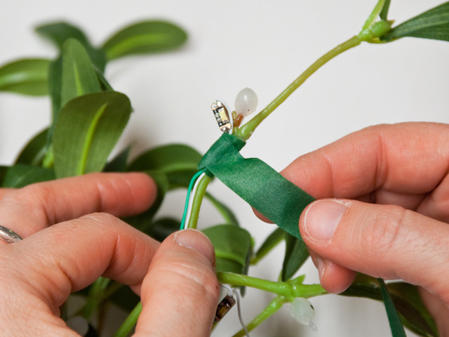


As you complete a row of LEDs, test their wiring with a small watch battery to be sure they work. Then, use floral tape to wrap each wired branch. Stretch the tape slightly as you go, so the tape adheres. Take the tape all the way to the end of the branch and cover the wires as best as you can. Now repeat wiring and wrapping for the other branches.
Solder Trinket and Sensor


Take the black (-) wire of the sensor and solder it onto the GND of Trinket on the reverse side of the board. Now gather all the negative wires (white), and twist the ends together until they form a single wire. It helps to rubberband the other wires out of the way. Tin the end of the white wires.

Solder the end of the white wires onto the GND of Trinket. Having problems? You can always cut a short piece of white wire and solder it to the GND on Trinket and then solder the 4 white LED wires to that. Just make sure to apply electrical tape or heat shrink tubing at the junction.

Continue to solder the rest of the wires to their correct pins on Trinket. Make sure not to trim the length of the wires on the sensor. You may need to adjust the height later once you hang the mistletoe, and it is better to keep it longer rather than shorter.
Finishing Touches

Using the floral tape, wrap the sensor wires, using the same stretching technique used doing the LEDs. Leave the last 1.5" bare so there is no tension near the Trinket.

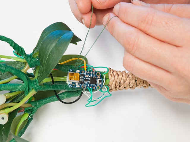
Cut a long piece of green wire and thread it through a mounting hole on the sensor, up through the center of the bundle, looping it near the top around a branch. Then, feed it down to the sensor's other mounting hole. It should hang just shy of the longest branches. Twist the wire to secure it.

Next, take the satin ribbon and tie a bow around the top of your bundle. Allow longer pieces to dangle on the sides. The bow helps to hide the electronics. You may want to take an extra piece of the ribbon and tie it to the top of the bundle for hanging, as well.


To prepare the battery, apply a strong tape around the top of the battery to protect the wires from stress. Then, make a holder from felt. Cut two pieces a little bigger than the battery and stitch the sides and the bottom. At the bottom, leave an opening large enough for the JST plug to dangle.


Now, use a Dremel to slice each berry in half. Then, using a hot glue gun, attach the berry slices, sandwiching the LED sequins. The idea is to use as little glue as possible to ensure that the LED can allow heat to dissipate. If you can't get hold of a Dremel, you can try getting opaque beads from a craft store, or experiment with little globs of hot glue applied to just one side of the LEDs.
Code
/* /////////////////////////////////////
 * Mistletoe Code modified by Leslie Birch with huge thanks to PIRsense Code from Arduino Playground
 * The base code is for the Parallax PIR Sensor, which is similar to the Adafruit PIR Sensor
 * @author: Kristian Gohlke / krigoo (_) gmail (_) com / http://krx.at
 * @date:   3. September 2006
 *
 * kr1 (cleft) 2006
 * released under a creative commons "Attribution-NonCommercial-ShareAlike 2.0" license
 * http://creativecommons.org/licenses/by-nc-sa/2.0/de/
 *
 *
 * The sensor's output pin goes to HIGH if motion is present.
 * However, even if motion is present it goes to LOW from time to time,
 * which might give the impression no motion is present.
 * This program deals with this issue by ignoring LOW-phases shorter than a given time,
 * assuming continuous motion is present during these phases.
 *
 */

/////////////////////////////
//VARS
//the time we give the sensor to calibrate (10-60 secs according to the datasheet)
int calibrationTime = 30;

//the time when the sensor outputs a low impulse
long unsigned int lowIn;

//the amount of milliseconds the sensor has to be low
//before we assume all motion has stopped
long unsigned int pause = 2000;

boolean lockLow = true;
boolean takeLowTime;

int pirPin = 0;    //the digital pin connected to the PIR sensor's output
int ledPin1 = 1;
int ledPin2 = 2;
int ledPin3 = 3;
int ledPin4 = 4;


/////////////////////////////
//SETUP
void setup(){
  //Serial.begin(9600);
  pinMode(pirPin, INPUT);
  pinMode(ledPin1, OUTPUT);
  pinMode(ledPin2, OUTPUT);
  pinMode(ledPin3, OUTPUT);
  pinMode(ledPin4, OUTPUT);
  digitalWrite(pirPin, LOW);

  //give the sensor some time to calibrate
  //Serial.print("calibrating sensor ");
    for(int i = 0; i < calibrationTime; i++){
    //  Serial.print(".");
      delay(1000);
      }
   // Serial.println(" done");
   // Serial.println("SENSOR ACTIVE");
    delay(50);
  }

////////////////////////////
//LOOP
void loop(){

     if(digitalRead(pirPin) == HIGH){
       digitalWrite(ledPin1, HIGH);   //the led visualizes the sensors output pin state
       delay (200);
       digitalWrite(ledPin3, HIGH);   //the led visualizes the sensors output pin state
       delay (400);
       digitalWrite(ledPin2, HIGH);   //the led visualizes the sensors output pin state
       delay (200);
       digitalWrite(ledPin4, HIGH);   //the led visualizes the sensors output pin state
       if(lockLow){
         //makes sure we wait for a transition to LOW before any further output is made:
         lockLow = false;
        // Serial.println("---");
        // Serial.print("motion detected at ");
        // Serial.print(millis()/1000);
       //  Serial.println(" sec");
         delay(50);
         }
         takeLowTime = true;
       }

     if(digitalRead(pirPin) == LOW){
       digitalWrite(ledPin4, LOW);  //the led visualizes the sensors output pin state
       delay (200);
       digitalWrite(ledPin2, LOW);  //the led visualizes the sensors output pin state
       delay (400);
       digitalWrite(ledPin3, LOW);  //the led visualizes the sensors output pin state
       delay (200);
       digitalWrite(ledPin1, LOW);  //the led visualizes the sensors output pin state

       if(takeLowTime){
        lowIn = millis();          //save the time of the transition from high to LOW
        takeLowTime = false;       //make sure this is only done at the start of a LOW phase
        }
       //if the sensor is low for more than the given pause,
       //we assume that no more motion is going to happen
       if(!lockLow && millis() - lowIn > pause){
           //makes sure this block of code is only executed again after
           //a new motion sequence has been detected
           lockLow = true;
           //Serial.print("motion ended at ");      //output
           //Serial.print((millis() - pause)/1000);
          // Serial.println(" sec");
           delay(50);
           }
       }
  }
Use it!

Time for mistletoe fun! Make sure the cable for the motion sensor is tucked up inside the bundle and that the sensor's lens is clear of leaves. Now, plug in the battery and tuck the case inside the top of the branches. Give the sensor about 30 sec. to calibrate and then try walking under the mistletoe. In a few seconds berries will light up.
Here are some other things to consider. I didn't have to adjust the settings on the motion sensor, but know that there are some listed in the PIR Motion Sensor Guide. Also, my floral tape was dark green, but really a lighter green would have blended better. If the color bothers you, consider dabbing some paint on the tape. Finally, there is a red LED that triggers on the Trinket when the motion sensor is in use. So, just put a small piece of dark tape over it and the magic will stay undiscovered.
Happy hacking!
This guide was first published on Dec 18, 2014. It was last updated on Dec 18, 2014.


