


Solder Headers
Align socket header pins to the Prop-Maker wing. Use a breadboard to help solder the short side of the headers to the Prop-Maker.
Solder socket headers to the top side of the Feather RP2040 board. Then, solder pin headers to the bottom side of the PropMaker FeatherWing so it can be plugged into the Feather.

Solder extension wires
Solder extension wires for the fan and power switch to the Prop-Maker. The fan plugs into a Molex PicoBlade socket extension cable.
LEDs and speakers wires plug into the ports on the board.
NeoPixel LEDs plug in via the 3 Pin JST cable on the Prop-Maker.


Speaker mount
Speaker press fits into the printed mount, facing up. Use M2.5x6mm long screws to attach to the top of the Prop-Maker board.
Coil wires
Coil wires for the fan and power switch under the Prop-Maker board.


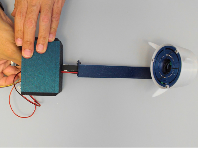
Fan mount
Sandwich the fan between the printed mount and the Feather mount. Use the included fan screws and nuts to secure the mounts.


Feather mount
Attach the Feather board to the fan mount with M2.5x6mm long screws.
Join the Prop-Maker headers to the Feather board socket headers.


LED rings
Solder wires to the back side of the LED rings.
Lay the 16 NeoPixel ring facing down on the printed mount.
Lay the 24 NeoPixel ring facing up and solder wires from the 16 ring to 24 ring.


LED Ring JST
Solder a 3 pin JST PH cable to the 12 ring LED, this will connect to the port on the Prop-Maker.
Mount fan
Use M2x12mm long screws to secure the LED ring mount to the Prop-Maker / Feather sandwich.
Connect wires
Plug in the wires for the LEDs, fan, switch and battery extension cable.


Align tabs
Pass the Prop-Maker circuit from the bottom (larger) end of the Rocket body. Gently press on the one side of the Rocket body to fit the mounting tabs inside the body.
Screw tabs
Tabs are aligned and secured with M2x6mm long screws


DIY USB cables
Use 30mm long DIY USB ribbon cable with a socket USB A on one side and USB C plug on the other side.


Mount pipe
Press wires into the mounting pipe. Use M2x6mm long screws to secure the Rocket body.
Attach Lid
Align the Pipe lid and press fit to the pipe opening.


Thread wires
Thread wires into the center opening on the case. Use M2x6mm screws to secure the Pipe to the case.


Rotary assemble
Align pins on the rotary encoder and solder to the board.
Mount rotary
Identify the LED on the Rotary board and align it to the slit opening on the case. Press the Rotary Stem through the opening on the case.
Fasten with the included nut and attach the cap to the stem.

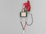


Power switch
Solder spade connectors to a 2 Pin JST socket to easily connect the toggle switch to an extension cable.
Mount switch
Press fit the stem into the case. Use the include nut to secure the switch cover to the case.

USB adapter
Attach a USB A to USB C adapter to the DIY USB socket.
The adapter press fits to the port opening on the case.
Use a magnetic USB C tip to easily attach a charging cable.
Connect an optional LiPo battery to the JST extension cable.
Case Lid
Align the opening on the lid to the USB port on the case. Press fit to secure.
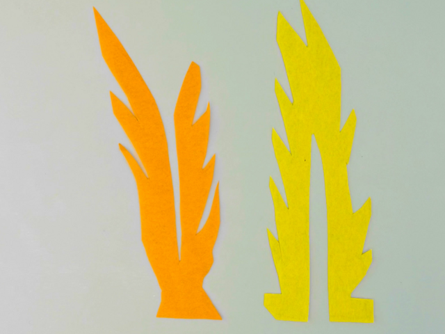


Flame assembly
Trace and cut out a flame design out of tissue paper.
Use double stick tape to adhere the ends to the bottom of the ring mount.


