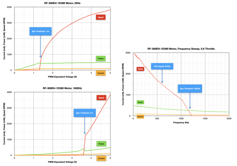
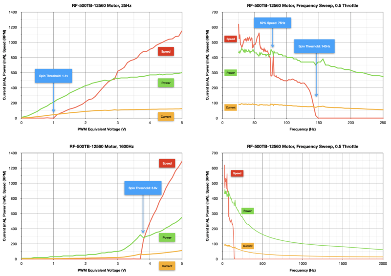
A lower PWM frequency can dramatically improve the slow-speed operation of brushed DC motors. Set your motor controller's PWM frequency below 100Hz and test to see if performance improves.

Parts

Angled Shot of the Assembled DC Motor + Stepper FeatherWing Add-on
A Feather board without ambition is a Feather board without FeatherWings! This is the Fully assembled (with headers) DC Motor + Stepper FeatherWing which will let...
$21.50
In Stock
Angled shot of a Adafruit Motor/Stepper/Servo Shield for Arduino v2 Kit connected to several different steppers and servos.
The original Adafruit Motorshield kit is one of our most beloved kits, which is why we decided to make something even better. We have upgraded the shield kit to make the bestest,...
Out of Stock
Angled shot of a Adafruit CRICKIT FeatherWing for any Feather
Sometimes we wonder if robotics engineers ever watch movies. If they did, they'd know that making robots into servants always ends up in a robot rebellion. Why even go down that...
Out of Stock
Top down view of a Adafruit CRICKIT for Circuit Playground Express with a circular board connected.
Sometimes we wonder if robotics engineers ever watch movies. If they did, they'd know that making robots into servants always ends up in a robot rebellion. Why even go down that...
Out of Stock
Video of a Adafruit DRV8833 DC/Stepper Motor Driver Breakout Board connected to a half sized white board powering a stepper motor with a adabot head spinning on it.
Spin two DC motors or step one bi-polar or uni-polar stepper with up to 1.2A per channel using the DRV8833. This motor driver chip is a nice alternative to the TB6612 driver. Like that...
$5.95
In Stock
Angled shot of a blue, square-shaped DC motor driver breakout with green pre-soldered terminal blocks.
Crank up your robotics with powerful Adafruit DRV8871 motor driver breakout board. This motor driver has a lot of great specs that make it useful for a wide variety of...
$7.50
In Stock
Video of a spinning motor driver connected to a Adafruit TB6612 1.2A DC/Stepper Motor Driver Breakout Board.
Spin two DC motors, step one bi-polar or uni-polar stepper, or fire off two solenoids with 1.2A per channel using the TB6612. These are perhaps better known as "
$6.95
In Stock
 L293D Dual H-Bridge Motor Driver for DC or Steppers
Run four solenoids, two DC motors, or one bi-polar or uni-polar stepper with up to 600mA per channel using the L293D. These are perhaps better known as "the drivers in our...
$8.95
In Stock
Feather wired to L9110 chip, driving a DC motor back and forth
Run two solenoids or a single DC motor with up to 800mA per channel using the super-simple L9110H H-bridge driver. This bridge chip is an 8 DIP package so it's easy to fit onto any...
$1.50
In Stock
robotics___cnc_StringCar_M0_Express_comp.png
StringCar M0 Express running CircuitPython

The StringCar racer robot was bouncing off the string when accelerating and braking. At slow speed, the precariously balanced car’s pulley dramatically changed speed and disengaged from the string without warning. To avoid sudden starts and stops, the car's CircuitPython code gradually ramped the motor voltage up and down using PWM (Pulse-Width Modulation) signals, so why was the car so jumpy?

It became obvious that the car's brushed direct-current (DC) motor didn’t have enough torque to run reliably at speeds less than 200RPM without some sort of gearing arrangement. A geared motor for the StringCar was too heavy and difficult to balance, so another solution was needed.

After some experimentation, the solution was to adjust one of the PWM signal characteristics. No need to add a gearbox or change hardware; we'll just apply a simple change in the CircuitPython code.

This guide will elaborate on the solution, examine some commonly available motors, and provide programming examples that will improve the low-speed performance of your robot’s brushed DC motors. First, we’ll look at the motors’ love/hate relationship with PWM and how to make them friends again.

robotics___cnc_DSC06300_2.jpg
The Insides: Motor Shell with Magnet Ring -- Rotor -- End Bell with Brushes

Brushed DC motors have an affinity for direct current. They are designed to spin in proportion to the applied DC voltage. For example, a miniature 6-volt DC motor runs at its full rated speed when supplied with power from four AA batteries (four times 1.5 volts equals 6 volts). The motor will run slower with three AA batteries (4.5 volts) or even slower with two AA batteries (3 volts). When the speed of a robot's DC motor needs to be controlled by software, swapping batteries in and out just won't do.

To control the motor with software like CircuitPython, a special signal called Pulse Width Modulation (PWM) is used. Microcontrollers such as the Feather M4 Express send a software-controlled PWM signal to an external breakout board in order to control motor speed. To cause the motor to spin, the microcontroller furnishes the external motor controller board a pulsing signal which in turn sends a high-power pulse to the attached motor. The width of each pulse is set by the program code to adjust the amount of energy for the controller board to send to the attached motor. A pulse with a long duration imparts more energy to the motor, increasing the speed of the motor. A short duration pulse reduces the available energy and the motor spins more slowly. The motor sees changes in pulse energy just like when batteries are added or removed. With a little math, the pulse energy can be expressed as an “equivalent voltage” similar to battery voltage. Let’s get to know the PWM signal better.

Duty Cycle is the ratio of the full-power pulse's duration to the entire PWM interval period, usually expressed as a percentage. PWM Equivalent Voltage is the product of the power supply voltage times the Duty Cycle divided by 100.

When a controller is sending the full voltage of the power source to the motor, the motor sees a PWM signal with a duty cycle of 100%. For example, if the controller output is always at the power supply voltage level, the duty cycle is 100%; if at full voltage for 5 milliseconds (ms) during a 10ms interval period , the duty cycle calculates to 50%. A full voltage pulse for 2ms during the 10ms period has a duty cycle of 20%.

PWM equivalent voltage is equal to the power supply voltage times the duty cycle. If the power source is 5 volts, a duty cycle of 100% has an equivalent voltage of:

5v * (100% / 100) = 5 volts

A duty cycle of 20% produces the equivalent voltage:

5v * (20% / 100) = 1.0 volts

As the PWM duty cycle changes, the motor reacts to the equivalent voltage and spins the motor at a speed that is proportional to that value. A lower duty cycle slows the motor; a higher duty cycle increases motor speed.

In CircuitPython's motor control libraries, the motor’s PWM duty cycle ratio is usually called the motor’s throttle, expressed as a numeric value between 0 and 1.0 where a value of 0 stops the motor and 1.0 runs the motor at full speed. Forward motor direction is a positive throttle value (0 to +1.0). Reverse direction is a negative value (0 to -1.0).

While duty cycle controls the motor’s speed, the PWM signal’s frequency effects the efficiency of a brushed DC motor, particularly when the PWM duty cycle is less than 30%. Why does the PWM frequency play a role? 

PWM Frequency is the count of PWM interval periods per second, expressed in Hertz (Hz). Mathematically, the frequency is equal to the inverse of the interval period's length (PWM_Frequency = 1 / PWM_Interval_Period).
robotics___cnc_DSC06293_2.jpg
Coils of Wire in the Motor's Rotor

After calculating the PWM Equivalent Voltage, we generally assume that the motor will operate ideally and respond as if it was connected to a non-PWM power source providing the voltage. But that's not the case. For example, a Yellow-TT motor will spin if a single 1.5-volt battery is connected, but will not turn until the PWM Equivalent Voltage coming from a Motor FeatherWing reaches 2.0 volts. And when it does start, it suddenly rotates at 4000 RPM. Why is that?

Since a brushed DC motor’s internal rotor consists of two or more coils of wire wound around laminated magnetic core material, the motor acts like an inductor. Depending on size of the rotor coil, it may take a few milliseconds for the energy to build sufficiently to turn the shaft.

Inductors are electromagnetic components that capture energy from the buildup of the magnetic field created by an electrical current passing through a wire coil.

Rotor coil inductance becomes a primary factor to consider when using PWM for motor speed control. The motor coil works best when the applied voltage is relatively steady since it needs time for its magnetic field to reach the needed strength. At higher PWM frequencies, the pulses from the motor controller board are changing too quickly to provide enough energy to spin the motor until the equivalent voltage reaches 2.0 volts.

When the PWM frequency is lowered, the motor’s coils extract more energy from the pulsed PWM signal. That means that the motor will start spinning at a lower equivalent voltage and will operate with improved torque at low speeds. The following graph compares the Yellow-TT motor's speed response when the default PWM frequency of 1600Hz is changed to 25Hz.

robotics___cnc_TT-Yellow_25-1600_Comparison.png
PWM Frequency Comparison: Yellow-TT Motor

The spin threshold at 25Hz starts at 0.3 volts, increasing the useable motor speed range to as low as 100 RPM. The Yellow-TT gearbox reduces the motor’s RPM by a factor of 48, so the attached wheel will be turning at 2 RPM or about 0.6cm/sec. A velocity like that will make it much easier for your robot to sneak up on the cat.

How do we choose the best PWM frequency for our robot’s motors?

robotics___cnc_Motor_datasheet_sample_pix.png
Manufacturer's Datasheet Performance Graph for the StringCar M0 Express' Motor

Motor manufactures’ data sheets provide excellent performance information about a motor’s optimum operating parameters such as voltage and current at the motor’s rated speed. Most manufacturers also provide tables and graphs that show how the motor responds to different voltages and the corresponding changes to RPM, torque, and power. However, very little information is available about how a particular motor responds to PWM signals.

We already know that PWM duty cycle can control a motor’s speed, but to understand what happens when the PWM frequency is varied, we need a way to measure the motor’s frequency response — much like that used to characterize an audio speaker (another electromagnetic device). If we have the motor’s frequency response spectrum, picking the best-performing PWM frequency is straightforward.

robotics___cnc_TT-Yellow_Frequency_Response.png
PWM Frequency Response Spectrum: Yellow-TT Motor

The PWM frequency response spectrum for the Yellow-TT motor shows the motor speed (the red line) as the PWM frequency is swept from 25Hz to 2000Hz. The throttle is held at 0.150 during the frequency sweep creating an equivalent voltage of 0.750 volts. At a PWM frequency of 25Hz, the chart shows the motor spinning at 4000 RPM. The speed reduces quickly as the frequency increases, dropping to one-half of the initial RPMs at 340Hz and completely stopping when the PWM frequency reaches 1200Hz. The chart indicates that a PWM frequency of 340Hz or lower will work nicely with low motor throttle settings.

Test the frequency you selected with the motor attached to your robot and operating with its normal power supply source. PWM frequencies of 60Hz or lower can cause mechanical vibration depending on the motor and the quality of its gearbox. Adjust the PWM frequency for the best balance of vibration and low-speed operation.

Frequency response charts for a variety of popular brushed DC motors can be found in the Motor Performance Charts section.

DIY: Finding the Optimal PWM Frequency

If you don't have a PWM frequency response chart for your motor, the simplest way to pick an optimal PWM frequency is to watch your robot motors in action at different PWM frequencies. Start at the lowest possible value (usually about 25Hz) and work up to the maximum (2100Hz). Choose the frequency that provides the best balance of torque throughout the desired speed range while balancing the motor chatter that can happen at lower frequencies.

Most small brushed DC motors will operate nicely with a PWM frequency of 50Hz to 100Hz. Projects that don't use gearbox motors, such as the StringCar racer, seem to work best at 25Hz.

robotics___cnc_Motor_Comparison.001.jpeg
Table of Important PWM Motor Characteristics

After characterizing a few brushed DC motors from the workshop inventory, the results concluded that a low PWM frequency will improve a motors' low-speed performance and overall speed range. All motors saw a significant reduction of spin threshold voltage when changing the PWM frequency from the MotorKit library's default of 1600Hz to a more compatible 25Hz.

The following charts show each motor's speed, power, and current characteristics as the motor tester swept through PWM Equivalent Voltage values and PWM frequencies. Let's walk through the first, the 1:20 Gearmotor with Encoder, to learn how to read each motor's chart collection. Click on the chart image for an enlarged view.

1:20 Gearmotor with Encoder

Angled view of a Geared DC Motor rotating while connected Circuitry shows RPM changing
The first step in a robotics project is to get a motor spinning. Once you've done that, you quickly learn that not all motors go the same speed, even if they are the same part...
$13.50
In Stock

The 1:20 gearmotor combines a high quality motor and gearbox with a quadrature magnetic encoder to measure motor shaft RPM and direction. It's quiet and smooth.

The two charts on the left show the results of sweeping the PWM equivalent voltage from 0 to 5 volts using a PWM frequency of 25Hz and 1600Hz. At the lower PWM frequency, the motor started spinning very slowly at 0.1 volts compared to 1.4 volts at the higher frequency.

The right-hand charts show the motor's response to changing the PWM frequency when the throttle was held at 0.150 (0.75 volts). The first of the two frequency response charts is a closeup of the PWM frequency spectrum from 20Hz to 600Hz; it's a detailed view of the frequency response chart just below it. The motor spins the fastest when the PWM frequency is 20Hz. It drops to 50% of that speed at 142Hz and completely stops spinning when the frequency reaches 508Hz. Note that the motor continues to draw current at frequencies above 508Hz even when not spinning.

robotics___cnc_7V_Gearmotor-Encoder_Summary_Graphs.png
1:20 Gearmotor with Encoder, Adafruit PID#4416

130-Size Toy/Hobby Motor

DC Toy Hobby Motor
These are standard '130 size' DC hobby motors. They come with a wider operating range than most toy motors: from 4.5 to 9VDC instead of 1.5-4.5V. This range makes them perfect...
$1.95
In Stock
robotics___cnc_130-Size_Motor_Summary_Graphs.png
130-Size Toy/Hobby Motor, Adafruit PID#711

RF-300-EH-1D390 CD Spindle Motor

This is a repurposed motor, typical of the smaller round, short-length motors used to spin CD/DVD spindles. The motor's operating range is 2.8 volts to 7.0 volts. The rated voltage of 3.9 volts produces a speed of 4400 RPM.

robotics___cnc_RF-300EH-1D390_Motor_Summary_Graphs.png
RF-300EH-1D390 CD Spindle Motor

RF-300FA-12350 CD Spindle Motor

Video of a CD DVD Spindle Motor spinning.
What's this? A record player for ants?? Not at all! This is a DVD/CD Spindle Motor, that thing that's inside a CD or DVD player, that turns the disc...
$1.95
In Stock
robotics___cnc_RF-300FA-12350_Motor_Summary_Graphs.png
RF-300FA-12350 CD Spindle Motor, Adafruit PID#3882

RF-500TB-12560 BoomerPong StringCar Motor

This is a round short-length motor typically used for small fans and CD/DVD drives. The motor's operating range is 6.0 volts to 12.0 volts. The rated voltage of 6.0 volts produces a speed of 2700 RPM.

This is the motor used for the 9-volt series of StringCar racers, including the classic BoomerPong.

Source: Jameco

robotics___cnc_RF-500TB-12560_Motor_Summary_Graphs.png
RF-500TB-12560 StringCar BoomerPong Motor

RF-500TB-18280 String Car M0 Express Motor

This is a round short-length motor typically used for small fans and CD/DVD drives. The motor's specified operating range is 3.0 volts to 6.0 volts. The rated voltage of 6.0 volts produces a speed of 5600 RPM.

The motor will operate reliably with voltages as low as 1.0 volts and is highly efficient at 3.0 volts.

This is the motor used for the LiPo battery powered series of racers, the modern StringCar M0 Express.

robotics___cnc_RF-500TB-18280_Motor_Summary_Graphs.png
RF-500TB-18280 String Car M0 Express Motor

Servo DC Motor

DC Motor in Micro Servo Body and 0.1" power cable
This tiny DC Motor in Micro Servo Body is an interesting motor - it's the same size and shape as our micro servo but it isn't a servo. It's...
$3.50
In Stock
robotics___cnc_Servo_DC_Motor_Summary_Graphs.png
Servo-Sized DC Gearmotor, Adafruit PID#2941

Blue TT Motor

TT Motor with Bi-Metal Gearbox
These durable (but affordable!) gearbox motors (also known as 'TT' motors) are an easy, low-cost way to get your projects moving. This is a TT DC Bi-Metal Gearbox...
$4.50
In Stock
robotics___cnc_TT-Blue_Summary_Graphs.png
Blue_TT Gearmotor, Adafruit PID#3801

Yellow TT Motor

DC Gearbox Motor - TT Motor with two long wires and yellow body
Perhaps you've been assembling a new robot friend, adding a computer for a brain and other fun personality touches. Now the time has come to let it leave the nest and fly on...
$2.95
In Stock
robotics___cnc_TT-Yellow_Summary_Graphs.png
Yellow_TT Gearmotor, Adafruit PID#3777

Uxcell-ux0188 Motor

This is a round long-length motor typically used for RC vehicles. The motor's operating range is 3.0 volts to 9.0 volts. The rated voltage of 6.0 volts produces a speed of 6300 RPM.

This is the noisiest and most unpredictable motor in the workshop's collection. It found a home in an audio-powered laser galvanometer project. Besides chattering bearings, the motor's internal windings vibrated as loudly as a small loudspeaker.

robotics___cnc_Uxcell-ux0188_Motor_Summary_Graphs.png
Uxcell-ux0188 Motor

The following CircuitPython code examples will sweep an attached motor's duty cycle from 0% to 100% in 2% increments in one direction. Each step of the duty cycle will hold for 1 second. The motor stops at the end of the code. During execution, the code prints the duty cycle as a throttle value for display in the REPL's Serial and Plotter windows. 

The first portion of each example imports the needed libraries and instantiates the motor controller with a new PWM frequency. Change the frequency value to select the one that works best for the attached motor.

Each motor controller is implemented differently, so refer to the example's code description to change the controller's frequency. The examples describe the frequency setting techniques when using:

  • Crickit FeatherWing and Crickit for Circuit Playground Express
  • Motor FeatherWing and Motor Shield
  • Breakout Boards and H-Bridge Chips

Crickit FeatherWing and Crickit for Circuit Playground Express

Upon initiation, the Crickit library sets the DC motor PWM frequency to 50Hz, useful for most brushed DC motors like the Yellow TT motor. It is possible to override the default if a custom PWM frequency is needed while still preserving the ability to use the Crickit library's motor statements such as motor.throttle.

The Crickit library also initially sets the controller's decay mode to FAST_DECAY. We'll change the decay mode to SLOW_DECAY to take advantage of the resultant performance improvement.

The Crickit uses two internal GPIO pins for each of the two DC motor controllers. The internal pins reserved for the motor controllers are 18, 19, 22, and 23. This is the section of the example code that changes the PWM to a custom value:

PWM_FREQ = 25  # Custom PWM frequency; Crickit min/max 3Hz/720Hz, default is 50Hz
DECAY_MODE = motor.SLOW_DECAY  # Set controller to Slow Decay (braking) mode
THROTTLE_HOLD = 1  # Hold the throttle (seconds)

motor1 = crickit.dc_motor_1
motor2 = crickit.dc_motor_2

motor1.decay_mode = DECAY_MODE
motor2.decay_mode = DECAY_MODE

ss = crickit.seesaw  # To access Seesaw motor pins
ss.set_pwm_freq(22, PWM_FREQ)  # Set motor1A pin to custom PWM frequency
ss.set_pwm_freq(23, PWM_FREQ)  # Set motor1B pin to custom PWM frequency
ss.set_pwm_freq(19, PWM_FREQ)  # Set motor2A pin to custom PWM frequency
ss.set_pwm_freq(18, PWM_FREQ)  # Set motor2B pin to custom PWM frequency

Line 1 defines the constant used for the custom PWM frequency value, followed by a constant that defines the controller's decay mode. A throttle holding constant (THROTTLE_HOLD) of 1 second is used later in the example code. The next lines define names for the two Crickit motor controllers. Defining the names also instantiates the motor pin definitions that will be changed.

In lines 8 and 9, the decay mode is set for each motor instance using the decay mode constant defined earlier. Next we'll access each motor controller pin individually and reset the default PWM frequency. For example, the first pin of DC_Motor_1's controller is updated in line 12:

ss.set_pwm_freq(22, PWM_FREQ)

The PWM frequency of each pin is then set to the custom value stored in the PWM_FREQ constant.

Example code for the Crickit FeatherWing and Circuit Playground Express Crickit:

# SPDX-FileCopyrightText: 2021 Jan Goolsbey for Adafruit Industries
# SPDX-License-Identifier: MIT

# Crickit PWM Frequency Example
# for Adafruit Crickit FeatherWing (#3343)
# and Circuit Playground Express Crickit(#3093)

import time
from adafruit_motor import motor
from adafruit_crickit import crickit

PWM_FREQ = 25  # Custom PWM frequency; Crickit min/max 3Hz/720Hz, default is 50Hz
DECAY_MODE = motor.SLOW_DECAY  # Set controller to Slow Decay (braking) mode
THROTTLE_HOLD = 1  # Hold the throttle (seconds)

motor1 = crickit.dc_motor_1
motor2 = crickit.dc_motor_2

motor1.decay_mode = DECAY_MODE
motor2.decay_mode = DECAY_MODE

ss = crickit.seesaw  # To access Seesaw motor pins
ss.set_pwm_freq(22, PWM_FREQ)  # Set motor1A pin to custom PWM frequency
ss.set_pwm_freq(23, PWM_FREQ)  # Set motor1B pin to custom PWM frequency
ss.set_pwm_freq(19, PWM_FREQ)  # Set motor2A pin to custom PWM frequency
ss.set_pwm_freq(18, PWM_FREQ)  # Set motor2B pin to custom PWM frequency
print("PWM frequency:", PWM_FREQ)  # Display internal PWM frequency

motor1.throttle = 0  # Stop motor1
motor2.throttle = 0  # Stop motor2
print((0,))  # Plot/print current throttle value
time.sleep(THROTTLE_HOLD)  # Hold at current throttle value

# Sweep up through 50 duty cycle values
for duty_cycle in range(0, 101, 2):
    throttle = duty_cycle / 100  # Convert to throttle value (0 to 1.0)
    motor1.throttle = throttle
    motor2.throttle = throttle
    print((throttle,))  # Plot/print current throttle value
    time.sleep(THROTTLE_HOLD)  # Hold at current throttle value

motor1.throttle = 0  # Stop motor1
motor2.throttle = 0  # Stop motor2
print((0,))  # Plot/print current throttle value
time.sleep(THROTTLE_HOLD)  # Hold at current throttle value

Motor FeatherWing and MotorShield

Upon instantiation, the adafruit_motorkit MotorKit class sets the DC motor PWM frequency to a default of 1600Hz and the controller's decay mode to FAST_DECAY. Changing the frequency and decay mode to a custom value is accomplished using a MotorKit parameter after instantiation.

PWM_FREQ = 25  # Custom PWM frequency; MotorKit min/maz 24Hz/2100Hz, default is 1600Hz
DECAY_MODE = motor.SLOW_DECAY  # Set controller to Slow Decay (braking) mode
THROTTLE_HOLD = 1  # Hold the throttle (seconds)

# Instantiate motor controller wing
motorwing = MotorKit(i2c=board.I2C(), address=0x60)
motorwing.frequency = PWM_FREQ  # Set custom PWM frequency
print("PWM frequency:", motorwing.frequency)  # Verify internal PWM frequency
motor1 = motorwing.motor1
motor1.decay_mode = DECAY_MODE

The first line defines the constant used for the custom PWM frequency value. A constant value for the decay mode is defined as SLOW_DECAY, followed by a throttle holding constant (THROTTLE_HOLD) that's used later in the example code. Line 6 is the typical statement used to instantiate the Motor FeatherWing or Shield. Line 7 updates the MotorKit PWM frequency parameter with the custom value stored in the PWM_FREQ constant.

After the motor is instantiated in line 9, the controller's decay mode is set to SLOW_DECAY.

Example code for Motor FeatherWing and MotorShield:

# SPDX-FileCopyrightText: 2021 Jan Goolsbey for Adafruit Industries
# SPDX-License-Identifier: MIT

# Motor FeatherWing PWM Frequency Example
# for Adafruit Motor FeatherWing (#3243) and Motor Shield (#1438)

import time
import board
from adafruit_motor import motor
from adafruit_motorkit import MotorKit

PWM_FREQ = 25  # Custom PWM frequency; MotorKit min/maz 24Hz/2100Hz, default is 1600Hz
DECAY_MODE = motor.SLOW_DECAY  # Set controller to Slow Decay (braking) mode
THROTTLE_HOLD = 1  # Hold the throttle (seconds)

# Instantiate motor controller wing
motorwing = MotorKit(i2c=board.I2C(), address=0x60)
motorwing.frequency = PWM_FREQ  # Set custom PWM frequency
print("PWM frequency:", motorwing.frequency)  # Verify internal PWM frequency
motor1 = motorwing.motor1
motor1.decay_mode = DECAY_MODE

motor1.throttle = 0  # Stop motor1
print((0,))  # Plot/print current throttle value
time.sleep(THROTTLE_HOLD)  # Hold at current throttle value

# Sweep up through 50 duty cycle values
for duty_cycle in range(0, 101, 2):
    throttle = duty_cycle / 100  # Convert to throttle value (0 to 1.0)
    motor1.throttle = throttle
    print((throttle,))  # Plot/print current throttle value
    time.sleep(THROTTLE_HOLD)  # Hold at current throttle value

motor1.throttle = 0  # Stop motor1
print((0,))  # Plot/print current throttle value
time.sleep(THROTTLE_HOLD)  # Hold at current throttle value

Breakout Boards and H-Bridge Chips

The adafruit_motor library's DCMotor class is the one to use with Adafruit motor controller breakout boards and H-bridge integrated circuits. Upon instantiation, the library works with the pwmio.PWMOut class to define which GPIO pins to use to drive the motor, set the 500Hz default PWM frequency and FAST_DECAY controller mode. We'll change the default frequency when the GPIO pins are defined and will change the controller's decay mode to SLOW_DECAY.

Refer to your selected breakout board's or H-bridge chip's learning guide for how to properly connect it to a microcontroller.

PWM_FREQ = 25  # Custom PWM frequency in Hz; PWMOut min/max 1Hz/50kHz, default is 500Hz
DECAY_MODE = motor.SLOW_DECAY  # Set controller to Slow Decay (braking) mode
THROTTLE_HOLD = 1  # Hold the throttle (seconds)

# DC motor setup; Set pins to custom PWM frequency
pwm_a = pwmio.PWMOut(PWM_PIN_A, frequency=PWM_FREQ)
pwm_b = pwmio.PWMOut(PWM_PIN_B, frequency=PWM_FREQ)
motor1 = motor.DCMotor(pwm_a, pwm_b)
motor1.decay_mode = DECAY_MODE

The first line defines the constant used for the custom PWM frequency value. Next, a constant value for the controller's mode is defined as SLOW_DECAY, followed by a throttle holding constant (THROTTLE_HOLD) that's used later in the example code. The two GPIO pins needed for the motor controller are defined next. Choose two pins that have their own unused PWM channel.

Lines 6 and 7 use pwmio.PWMOut to establish the pins and set the custom PWM frequency. After the motor is instantiated as motor1 in line 8, the controller's decay mode is set to SLOW_DECAY.

Example code for breakout motor controller boards:

# SPDX-FileCopyrightText: 2021 Jan Goolsbey for Adafruit Industries
# SPDX-License-Identifier: MIT

# Breakout PWM Frequency Example
# for Adafruit motor controller breakout boards and H-bridge drivers
# TB6612 (#2448), DRV8833 (#3297), DRV8871 (#3190), L9110 (#4489), L293D (#807)

import time
import board
import pwmio
from adafruit_motor import motor

PWM_PIN_A = board.D5  # Pick two PWM pins on their own channels
PWM_PIN_B = board.D6
PWM_FREQ = 25  # Custom PWM frequency in Hz; PWMOut min/max 1Hz/50kHz, default is 500Hz
DECAY_MODE = motor.SLOW_DECAY  # Set controller to Slow Decay (braking) mode
THROTTLE_HOLD = 1  # Hold the throttle (seconds)

# DC motor setup; Set pins to custom PWM frequency
pwm_a = pwmio.PWMOut(PWM_PIN_A, frequency=PWM_FREQ)
pwm_b = pwmio.PWMOut(PWM_PIN_B, frequency=PWM_FREQ)
motor1 = motor.DCMotor(pwm_a, pwm_b)
motor1.decay_mode = DECAY_MODE

motor1.throttle = 0  # Stop motor1
print((0,))  # Plot/print current throttle value

# Sweep up through 50 duty cycle values
for duty_cycle in range(0, 101, 2):
    throttle = duty_cycle / 100  # Convert to throttle value (0 to 1.0)
    motor1.throttle = throttle
    print((throttle,))  # Plot/print current throttle value
    time.sleep(1)  # Hold at current throttle value

motor1.throttle = 0  # Stop motor1
print((0,))  # Plot/print current throttle value

Using the Adafruit_Motor_Shield_V2_Library

To adjust the PWM frequency of the Motor Shield or Motor FeatherWing, refer to the Arduino code example for the Adafruit_Motor_Shield_V2_Library: 

DC Motor Test Example

Using this library, the frequency can be changed from the default 1600Hz by including the new value in the begin statement:

AFMS.begin(100); // Set the PWM frequency to 100Hz

Note that, at this time, the library does not provide a parameter for changing the default controller decay mode from FAST_DECAY to SLOW_DECAY.

Using the analogWrite() Function

The PWM frequency of microcontroller GPIO pins using the analogWrite() function is fixed and cannot be changed. PWM signals sent directly to a motor controller breakout from GPIO pins will default to a frequency of 490Hz to 1000Hz depending on the microcontroller board used. See Arduino Reference: analogWrite() for more information.

To fully characterize a motor’s frequency response curve scientifically, an appliance for measuring motor performance is essential. At a minimum, measuring motor RPM under load while varying the PWM frequency will yield the frequencies where motor speed begins to drop and stall. A more sophisticated testing appliance adds sensors for measuring voltage, current, power, and torque.

robotics___cnc_Motor_Tester_Conceptual_Design.png
Motor Tester Conceptual Design

The motor tester used for this Learning Guide consisted of six fundamental components:

robotics___cnc_DSC06312.jpg
Motor Tester Final Version

The motor tester's code, written in CircuitPython, exercises the test motor, applies a braking current to the brake motor to simulate a load, and measures the current drawn by the test motor. In addition, motor speed and torque are recorded throughout the test.

The data used to create the collection of performance charts for this learning guide were captured by this apparatus.

This guide was first published on Feb 23, 2021. It was last updated on Mar 08, 2024.