


Solder three small wires to the Polar heart rate receiver, and stick it to the FLORA main board with a piece of double-stick tape or foam.


Wire up and solder the sensor to the FLORA main board according to the circuit diagram on the previous page.
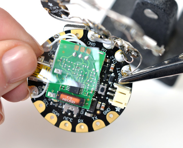


Place a piece of tape over the sensor to prevent the pixel display from shorting its contacts. Lay out and solder together your heart-shaped pixel display according to the circuit diagram on the previous page, then solder the heart shape to VBATT, GND, and D12 on the FLORA main board.
If using the LED matrix instead, solder it up according to the LED Backpack guide, then wire it to FLORA's 3.3v, SCL, SDA, and GND pins according to the circuit diagram.
If using the LED matrix instead, solder it up according to the LED Backpack guide, then wire it to FLORA's 3.3v, SCL, SDA, and GND pins according to the circuit diagram.

Stick the metal bar of the magnetic pin back on the back of the board, and use another piece of double-stick tape to attach the small lipoly battery right next to it.


