Epoxy resin river tables can be stunning works of art.  Adding NeoPixels and a Circuit Playground give this table an extra special dimension -- its soft pulsing glow fills a room with beauty and makes every meal into a masterpiece. 

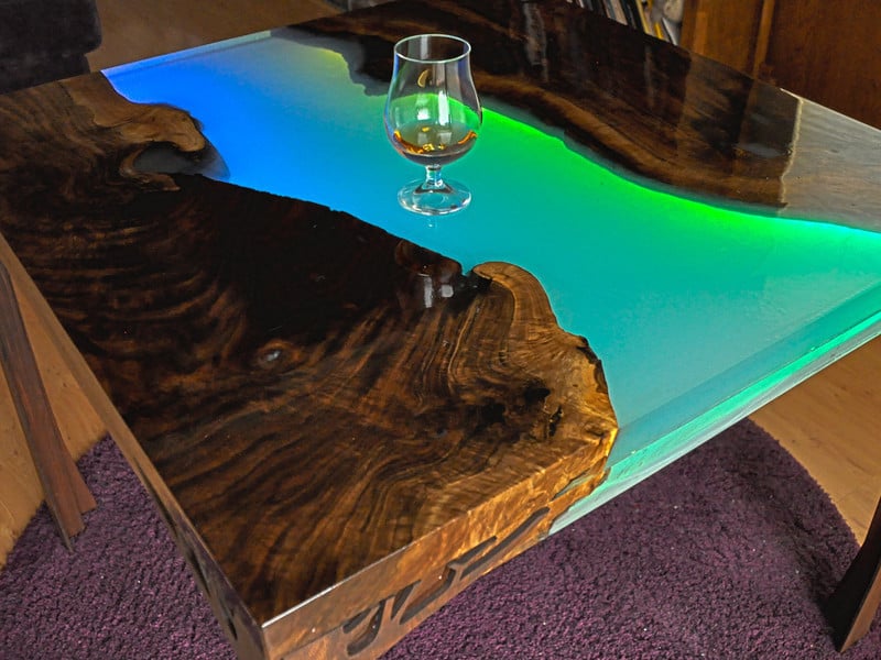
I love waking up with the sunrise and sipping tea with the softly glowing river beneath my mug, and coming home at night to eat a delicious meal set off by the gorgeous wood grain and slowly shifting rainbow colors.  It's the centerpiece of my living space and it brings me joy every single day.

This was my first attempt at building furniture and I'm very pleased with how it turned out.  This was not an easy build!  The electronics are fairly simple and straightforward, but the woodworking and larger-scale resin pouring was new territory for me, and I made a lot of mistakes (but I sure learned a lot!)  I would love to see an experienced woodworker take this idea and run with it!

Electronics Materials

1 x Circuit Playground Express
Microcontroller to make the lights work
2 x Neopixel Strip
60/m Skinny Neopixels
1 x Power Supply
4A is a good size for 2m of NeoPixels
1 x Screw Terminal
For connecting the power to the pixels
1 x JST Connector
Female JST Battery Connector

Table Materials

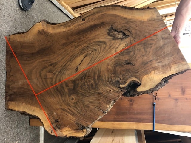
  • A slab of live-edge wood -- I used walnut.  Look for local suppliers and spend a fun afternoon perusing the selection.
  • Deep Pour Epoxy Resin -- you'll need a lot. 
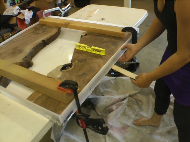
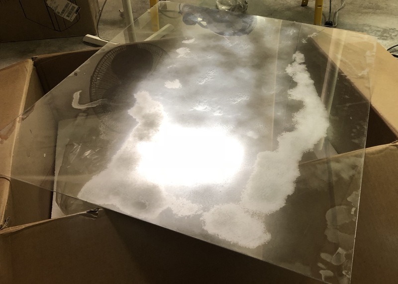
  • Polyethylene plastic for building your pour mold -- I got this at my local Tap Plastics, cut to size
  • Hot Glue for building the pour mold
  • Dye or color for the resin (optional) - I found some blue resin dye at my local craft store in a dropper bottle
  • Propane torch (or creme brulee torch) for getting rid of bubbles
  • Mixing buckets, gloves, stirring sticks, lots and lots of drop cloths and cleanup gear
  • Woodworking tools for prepping and sanding the wood

Other Build Materials

Data Connection

The Circuit Playground must be connected to the "in" end of the LED strip.  Data flows one way through the strip, from "in" to "out".

  • Circuit Playground G --> Neopixel G
  • Circuit Playground A1 --> Neopixel IN

Power Connections

The power supply will be connected directly to the strip, so power doesn't need to all flow through the Circuit Playground.  Drawing too much current through a microcontroller can be problematic, so it's good practice to run the power directly to the NeoPixels if you have a long strip. 

Connect the + and - wires from the screw terminal to both the NeoPixel strip + and -, and to the Circuit Playground's battery port.

Powering

Choose an appropriate power supply to support the number of LEDs you have.  A small 2A power supply will work fine for up to around 60-80 pixels.  If you have 150-200 like me, you may have better success with a 5A or larger power supply.  Just remember that whatever supply you use, you must give the project 3.7-5V.  Any larger voltage will fry your pixels, or a lower voltage won't be adequate to run them.

Head over to the Neopixel Uberguide to learn more about power requirements.  For up to around 200 LEDs I found the 5v 4A power supply to be totally sufficient.

MakeCode is an easy way to get up and running with the Circuit Playground Express.  No prior coding knowledge is needed, and it's an easy way to experiment and learn to think like a coder.

To get started, go to makecode.adafruit.com and then choose New Project.  You'll find yourself in the MakeCode Editor.  From here, you can click on any of the colored tabs and drag blocks of code onto your workspace, then preview it using the Circuit Playground Express pictured on the left.  

Once your code is written, plug your Circuit Playground Express into your computer via its USB port and click the "reset" button.  All the lights will turn green and your Circuit Playground will appear as a drive on your computer called CPLAYBOOT.  Simply drag your downloaded code onto this drive to program the Circuit Playground Express.  Easy! Note: If you see a drive called CIRCUITYPY then press the reset button again (or twice in a row) to get to CPLAYBOOT.

Head over to this Intro to MakeCode guide for more info on getting started with MakeCode.

If you want to skip right to the end and work backwards, here's the completed MakeCode project.

Set Up the Lights

First, let's tell the Circuit Playground that we have a strand of lights wired up to pin A1, and how many pixels we're using.  We'll also set the brightness of our lights. 

It's good practice to use a variable to tell the Circuit Playground how many lights will be used.  That way if the number of pixels in the strip changes later on, or if we want to reference it later in the code, it can be done easily.   To do this, go to the VARIABLES tab and create a new variable.  Call it numpixels.  Then drag an instance of set item into your on start loop and select your numpixels variable.  Set the number of pixels in your strip.

Next, add the strip itself.  From the VARIABLES tab, drag another instance of set item into your on start loop, and this time select the strip variable.  (If it's not there, go ahead and create it.) 

Click the LIGHT tab to make the NEOPIXEL tab appear beneath it.  Anything in the NEOPIXEL tab will refer to the strip of lights you attached, and anything in the LIGHT tab refers to the lights on the face of the Circuit Playground Express. 

Drag an instance of create strip into your set strip line, and click the + sign to set it up as shown.

Drag an instance of strip set brightness into your on start loop (from the LIGHTS tab).  Set your brightness to something moderate for now -- you can always change this later.  I used 150 which is a little more than 50% bright.  Depending on the environment where your table will be, you may want to choose as low as 40, so people can still see their food.

Create a Toggle Variable

The Circuit Playground Express has two buttons on the face, a slide switch, or a number of capacitive touch pads.  Any of these can be used to control our lights.  I'm mounting the board underneath my table, so I decided to use the buttons since they're easy to find with my fingers when I can't see the board.   

Another great idea might be to make a capacitive touch inlay in the table and control the Circuit Playground with that, as shown in this awesome Metal Inlay Capacitive Touch guide.

First we need to create a variables.  Go to your VARIABLES tab and create a variable called on.  We'll use this to hold the state of the lights, so we can tell if they're on or off.

Drag another instance of set item into your on start loop, and choose your on variable.  Then, under the LOGIC tab, choose true.  This will make the lights default to on when you plug the table in.

Add Animation

MakeCode comes with six different pre-programmed animations to choose from, or you can create your own in Javascript or using the Photon feature.  I used the rainbow animation in my example, but play with the others too, and see if there's something you like!

We'll add the animation in the forever loop, so it runs continuously.  But we only want it running when the table is turned on, so for this we'll need to add a conditional loop.  

Under the LOGIC tab, drag an if / then / else block into your forever loop.  Add a comparison block and drag in variables and logic so it reads if on = true then

Now, tell it what you'd like it to do if on=true: run some animation.  Under the LIGHTS tab, drag strip show animation into the first part of the conditional loop.  Set the delay to 100ms.  The animation will keep running the whole time the table is on, but every 100ms the Circuit Playground will check to see if its button has been pressed -- so a smaller delay here means a more responsive button.

To make the lights go off when on=false, drag an instance of strip set all pixels to into the else part of the conditional block, and change the color to black.

Code the On/Off Switch

We'll use one more conditional loop to make our on/of toggle switch.  From the INPUT tab, drag an instance of on button A click onto your workspace.  Put a conditional loop inside (from the LOGIC tab) and add your variables as shown.  Now, each time the button is clicked, the on variable will change state from true to false.  This will make the lights toggle on and off as it works together with the conditional in the forever loop.

Since my Circuit Playground Express will be mounted below my table where I can't see it, I want to be able to use either button to turn it on or off.  Select the on button A click block and copy/paste it to your workspace.  Then choose button B instead of button A.  This way both buttons will work as toggle switches.

Save your work, and click the Download button in the lower left corner.  Plug in your Circuit Playground and press the reset button.  The onboard NeoPixels should all turn green, and you'll see a new drive appear on your computer called CPLAYBOOT.  Drag the file you downloaded onto this drive.  You're done!

If you're having trouble or don't see the CPLAYBOOT drive, head over to the Circuit Playground Express guide for some troubleshooting tips.

For more advanced users, or if you want more control over colors and modes, Arduino using the FastLED library is a great way to go.  FastLED is a robust library with lots of fancy functions and lots of code samples to choose from.  If you want custom animations and color palettes, this is the top-of-the-line.

The code I've uploaded will cycle through 5 different color modes either automatically (changing every 60 seconds) or when you press the left button on the Circuit Playground Express.  The right button will turn the LEDs off.

Before You Start

If this is your first foray into the world of arduino-based microcontrollers, you'll need to install some software first. Head over to the Circuit Playground Lesson 0 guide for detailed installation and setup instructions.  

You'll only need to do all this once, so be a little patient if it seems like a lot!

FastLED Library

You will also need to install the FastLED library in Arduino (Sketch > Include Library > Manage Libraries...)

One other note:  if you're using FastLED with Circuit Playground Express, be sure to #include the Circuit Playground library FIRST and the FastLED library second, or you may run into problems.

Upload Code

Once you've got everything installed and your computer can talk to the Circuit Playground Express, it's time to upload the code.

Plug your Circuit Playground Express into your computer and select the Circuit Playground Express under Tools > Boards.  Then select the port identified as Circuit Playground Express.

Copy and paste this code into a new Arduino window and click "upload".

// SPDX-FileCopyrightText: 2013 FastLED
// SPDX-FileCopyrightText: 2018 Erin St Blaine for Adafruit Industries
//
// SPDX-License-Identifier: MIT

// Code by Erin St Blaine for Adafruit.com, based on FastLED animations by Mark Kriegsman

#include <Adafruit_CircuitPlayground.h>
#include <FastLED.h>

// tell FastLED all about the Circuit Playground's layout

#define DATA_PIN     A1    //LED data on pin A1
#define NUM_LEDS    200   // total number of LEDs in your strip
#define COLOR_ORDER GRB  //  color order -- change this if your colors are coming out wrong

uint8_t brightness = 150;  // Set brightness level

int STEPS = 6;  //makes the rainbow colors more or less spread out
int NUM_MODES = 5;  // change this number if you add or subtract modes
int CYCLETIME = 60;  // number of seconds on each mode, for mode cycling

CRGB leds[NUM_LEDS];      // set up an LED array

CRGBPalette16 currentPalette;
TBlendType    currentBlending;

int ledMode = 0;       //Initial mode 
bool leftButtonPressed;
bool rightButtonPressed;


// SETUP -----------------------------------------------------
void setup() {
  Serial.begin(57600);
  CircuitPlayground.begin();
  FastLED.addLeds<WS2812B, DATA_PIN, COLOR_ORDER>(leds, NUM_LEDS).setCorrection( TypicalLEDStrip ); // Use this line if using neopixels
  currentBlending = LINEARBLEND;
  set_max_power_in_volts_and_milliamps(5, 5000);               // FastLED 2.1 Power management set at 5V, 5000mA

  
}

void loop()  {

  leftButtonPressed = CircuitPlayground.leftButton();
  rightButtonPressed = CircuitPlayground.rightButton();

  if (leftButtonPressed) {  //left button cycles through modes
    clearpixels(); 
    ledMode=ledMode+1;
    delay(300);
    if (ledMode > NUM_MODES){
    ledMode=0;
     }
  }
    if (rightButtonPressed) {  // on off button
    ledMode=99;
  
    }
  
 switch (ledMode) {
       case 0: modeCycle(); break;
       case 1: currentPalette = RainbowColors_p; rainbow(); break;
       case 2: currentPalette = OceanColors_p; rainbow(); break;                    
       case 3: currentPalette = LavaColors_p; rainbow(); break;   
       case 4: currentPalette = ForestColors_p; rainbow(); break;
       case 5: currentPalette = PartyColors_p; rainbow(); break;
       case 99: clearpixels(); break;
       
}
}
void clearpixels()
{
  CircuitPlayground.clearPixels();
   for( int i = 0; i < NUM_LEDS; i++) {
   leds[i]= CRGB::Black;
    }
   FastLED.show();
}

void rainbow()
{
  
  static uint8_t startIndex = 0;
  startIndex = startIndex + 1; /* motion speed */

  FillLEDsFromPaletteColors( startIndex);

  FastLED.show();
  FastLED.delay(20);
  
  }

//this bit is in every palette mode, needs to be in there just once
void FillLEDsFromPaletteColors( uint8_t colorIndex)
{ 
  for( int i = 0; i < NUM_LEDS; i++) {
    leds[i] = ColorFromPalette( currentPalette, colorIndex, brightness, currentBlending);
    colorIndex += STEPS;
  }
}


int cycleMode=0;

void modeCycle()
{
   switch (cycleMode) {
       case 0: currentPalette = RainbowColors_p; rainbow(); break;
       case 1: currentPalette = OceanColors_p; rainbow(); break;                    
       case 2: currentPalette = LavaColors_p; rainbow(); break;   
       case 3: currentPalette = ForestColors_p; rainbow(); break;
       case 4: currentPalette = PartyColors_p; rainbow(); break;
       case 5: cycleMode=0; break;
}

   EVERY_N_SECONDS(CYCLETIME) {
    cycleMode++;
   }
   
}

If all goes well, the lights on the Circuit Playground will come on.  Press the right side button to turn the lights on and off.  Press the left side button to toggle between color modes.  

The initial mode will cycle through five different color modes, changing every 60 seconds.  Change this duration in the code with the CYCLETIME variable.  

The other modes use FastLEDs built in color palettes for a variety of different looks.

Add your own modes or customize the modes that are already there.  If you want to add your own color palettes, check out this Neopixel Parasol guide for ideas and instructions on how to do that with FastLED.

Plug your male JST connector into the female JST on the IN end of your NeoPixel strip.  This will help make sure you get the wires lined up and soldered to your Circuit Playground the correct way.  Solder the wire connected to the black wire (G) coming from the NeoPixels to the G pin on your Circuit Playground.  Solder the other wire (connected to the white wire on the NeoPixels) to pin A1.

Next we'll add the JST connector.  It works best to make a 3-way splice.  Twist the red wire from your JST connector together with the red wire coming from the NeoPixels, and solder on a third red wire which will connect to the screw terminal.


Do the same thing with the black wires.

Plug your Circuit Playground in with both connectors.  If you've already uploaded your code, the lights should come on when you connect your power supply.  

Troubleshooting

If you're reasonably certain you've got everything set up right, but your lights aren't working as expected, the most likely culprit is the screw terminal.  Try wiggling the wires connected here, or pulling them out and putting them back in again.  These things can be a bit twitchy.  I went through three different ones before I found one that worked reliably (so, maybe order a few when you're getting started!).

If that's not the problem, check to be double-sure you're soldering the data wire to the IN end of the Neopixels.  It won't work the other way.  And make sure your connector is soldered up correctly and that you haven't mixed up the G and Data wires.

I didn't want lights across the end of my table, so I split my light strand in two.  If you want to do this, carefully cut through the solder pads between any two LEDs and add a wire extension.  Be sure you're soldering from the OUT end of one strip to the IN end of the other -- so, the easiest way to think of this is to keep the wires connecting the two LEDs you just cut between.  Solder a red wire to +, a black wire to G and a white wire from OUT to IN.

There are countless online tutorials that will cover building a resin river table in detail.  I recommend watching a bunch of them, and finding a method that will work with your available tools and space.  I'll go briefly over the steps I took to build this one and point out a few of the mistakes I made, in hopes that you, dear readers, can avoid them.  

Preparing the Wood

I got a slab of live-edge walnut from a local supplier.  I asked them to cut the wood to give me enough for a 36" square table -- the size of the ratty old card table previously in residence in my kitchen dining area.

I took the wood to my local makerspace, Hackerlab, and ran it through the drum sander until I had an even thickness on both pieces and the wood was as flat as I could make it.  This took approximately 100 years.  Next time I will use the planer.

Building the Resin Mold

I went to my local Tap Plastics and asked them to cut me a sheet of polyethylene plastic that was 36 inches square, plus four side panels that would fit around the edges to build a mold for my table.  Polyethylene is perfect for this, since the resin will not stick to it and it's not too expensive.  I used hot glue and aluminum tape to hold the sides to the bottom. 

It was tricky to get this built water-tight so the resin wouldn't leak through, since the bottom of the mold was the exact size I wanted to end up with.  If I were to do it again, I'd make the bottom of the mold a few inches bigger.  I would make a 38" square and then secure the sides set-in by 2" to create a 36" box.  This would have given more plastic for the hot glue to grab around the edges -- I could have really piled it on to stop all the leaks -- and made my life easier.

How Much Resin to Get

I placed the wood into the mold and then filled the empty space with something I could easily measure the volume of.  Rocks, sand, or gravel would work great here.  What I had a lot of on-hand was cat food.  So I filled the river with cat food, then measured how much I'd used.  

For my 36" square table I ended up needing around 4 gallons of resin.  I ordered extra!  You'll need extra.  Order extra.

Clamp the wood down into the mold so it doesn't float up on top of the resin.  Be sure it's level, using shims to adjust the mold where needed.


Vacuum out ALL the dust.  Dust is the enemy!  The cleaner you can keep your environment, the better.  Every speck of dust that gets in the resin will show.  

Sealing the Wood

A lot of beautiful live-edge hardwoods have knots and cracks throughout the grain.  This makes them especially beautiful and unique, but will be your worst nightmare during a resin pour.  If you don't get all these holes filled up with cured resin, you'll get very annoying bubbles in your final pour as the resin seeps into the cracks. 

Before you do your first pour, mix up a small batch of resin and fill all the cracks and holes in your wood.  If the resin drips all the way through, put a piece of aluminum tape on the back side of the wood to hold the resin inside until it cures.  

You may be surprised at how much resin the wood will swallow up!  Some of these little holes apparently lead to other universes.

Pouring the Resin

Read and follow the manufacturer's directions carefully.  Resin can be finicky and if mixed incorrectly will remain a sticky mess forever!  That's the last thing you want on your expensive beautiful live-edge wood.  Each type of resin varies, but some general rules you don't want to bend include:

  1. Measure precisely.  Don't guesstimate!  You can get disposable graduated mixing buckets at any hardware store, so buy a stack of them and pay attention to the markings.
  2. Mix Thoroughly.  Mix for far longer than you think you need to.  Pour into a new container and mix again.  Unmixed resin will give you sticky spots.
  3. Pay attention to the temperature ranges and don't try and mix resin on a freezing cold day, or it won't ever set up.
  4. Pour the resin in multiple layers.  A too-thick layer will cause problems -- bubbles will get trapped in there, and it won't set up as well.  I found a 1/16" to 1/8" layer was about right.

I got my resin from several different sources.  Some, I had on-hand from earlier craft projects.  I found some on Amazon and ordered some directly from the manufacturer.  For the final pour I used resin from the craft store (since I ran out of the other stuff).  I was nervous the different kinds might not play well together, but they worked just fine.  I'd probably still advise to use just one kind of resin if you can, but being a bit promiscuous with resin types didn't hurt my project any.

I added some blue mica powder and some dye to my very first layer, to make it a little bit more opaque for better LED diffusion.  This looked lovely!  I made each subsequent layer more and more clear.

After each pour, I used a propane or butane torch just above the surface to pop any bubbles.  I tried using a heat gun at first, and that worked okay, but then I switched to the torch and it worked SO much better.  The open flame changes the oxygen / CO2 balance in the air which yanks the bubbles right out of the resin.  This part was so satisfying!

Cover between pours to minimize dust and hair getting into the resin. Let each pour cure for the time recommended on the directions.  Longer works fine too, but if you do leave it longer you'll want to sand each layer (and vacuum up all the dust) so the next layer has something to grab.  Don't worry about putting scratch marks in each layer.  The next layer will render them invisible.  This is handy -- you can sand out any bubbles or dust that snuck into any previous pours.

I filled my resin river and then did a final pour where I covered the whole table top with resin.  Unfortunately I got a little greedy here and poured my last layer too thick.  I also hadn't adequately sealed every hole and crack in the wood.  The result was that my top layer looked horrible.  It wasn't smooth, and there were dozens of ugly bubbles trapped just below the wood.  I got my rotary sander and tried sanding them out, but the resin was tough and I nearly gave in to despair and scrapped the whole project.  

But, after asking the advice of some local woodworkers at my makerspace, I decided to try using the CNC router to plane the table down and give the top layer another try.

I used a Shopbot CNC router to mill down both the top and the bottom of the table so they were perfectly flat.  This took off the bottom opaque layer of resin, but I could live with that.  

I used a table saw to neatly trim 1/4" off each side of the table.  This cleaned up the edges where the resin was uneven, and gave me four 1/4" edge pieces that matched the edges of the table perfectly.  I later used these as a "skirt" underneath the tabletop to hide the acrylic sheet and electronics.


I sanded down the bottom of the resin but did NOT do another thin coat of resin on the bottom of the table.  This might have looked beautiful -- it would make the whole table clear and see-through.  But I wanted a bit of cloudiness for diffusion so I left it sanded and not refinished.

The CNC router had reopened some of the holes in the wood, so I resealed using some resin, and where that didn't seem to work, I used a few dabs of 5-minute epoxy glue.  It didn't dry perfectly clear, but it did work to block the holes that would not fill up with resin (because, apparently, they led to some other dimension).

For the final pour, I moved the project into a dust-free room (my wine cellar), micromanaged the temperature, and did everything I could to create the perfect environment for a smooth pour.  

I warmed the resin in a hot water bath to thin it and lower the viscosity.  I used a squeegee to spread it as evenly as I could to all four corners, and a foam brush to add a thin coat to the sides.  

It's not perfect.. but it's good enough for me.  And for Biskit.

I want the table to look pretty while the lights are off as well as on.  The electronics are mounted below the table top, so I need a design which gracefully hides the electronics while letting as much light through the table as possible.  

I used 2x2 pine boards for the weight-bearing legs, staining them a nice matching walnut color.  

I used a laser cutter to cut 8 decorative legs from birch plywood.  I stained these to match the pine board legs and then glued them together using wood glue.

I added angle brackets to the weight-bearing pine legs and then screwed the legs onto the table, being sure to carefully line up the laser cut trees so they were perfectly flush with the edge of the table.

Next I trimmed the four "skirt" edge pieces down to fit, then glued them in place on the inside of the laser-cut trees, flush with the underside of the table.  I clamped them in place until the glue dried.  

Acrylic Plexiglass Platform

I want my LED lights to shine through with beautiful diffusion, but also to allow some ambient light to shine through the resin when the lights are turned off.  To achieve this, I suspended a plexiglass platform an inch or so below the table, with the light strips glued to it, facing inwards.  

I cut the plexiglass so it runs the full length of the underside of the table, fitting neatly between the skirt pieces.  It's not as wide as the table, but that works out fine -- it just needs to be big enough to fully cover the river section, not the whole table.

I placed my plexiglass on top of my table and sketched out where I wanted the lights to go with a sharpie.  Then I sprayed two coats of Mirror Effect spray paint by Rustoleum into the area between the lines.  This creates a one-way mirror effect -- the mirror spray reflects the lights upward to diffuse them really well, without blocking all the light coming up from below.

Next I glued the LED strips to the plexiglass along the lines.  I made them about an inch wider than the actual resin river so you can't easily see the individual LEDs from above.

The silicone strips encasing the LEDs make this a bit tricky. Hardly anything sticks to silicone!  The best thing I've found for this is Devcon Silicone Adhesive.  This stuff is magic -- nice and thick and goopy, and seems purpose-made for sticking NeoPixels to just about anything.

I used 2" wood screws to secure the acrylic sheet to the bottom of my table.  I carefully drilled four holes in the acrylic, outside the "river" area.  Acrylic cracks really easily!  Then I screwed the sheet to the underside of the table, leaving about an inch gap between the table and the acrylic with the LEDs positioned right below the resin river.

The objective here is to have enough space between the plexiglass and the table for diffusion, but still hide the whole electronics assembly inside the "skirt" I made out of the table sides.

I threaded the Circuit Playground Express around to the underside of the acrylic and stuck it on with a square of sticky-back velcro.  I added some heat shrink filled with hot glue to the screw terminal to keep the wires firmly in place, then used staples to secure it to the wood of the table. I ran the power cord down along the inside of the table leg to the floor and attached it with staples as well.

Once all the glue dried, I turned the table upright and plugged it in.  Suddenly all the imperfections, bubbles, streaks, and wobbles ceased to matter.  This thing is stunning.   I want to write a novel at it.  I want to serve exquisite fine food and wine to interesting people while engaging in witty conversation.  If I could invite three Notable Personages from History to a dinner party, I'd seat them at this table.  It's a table worthy of a fairy queen or a Narnian King.  

This guide was first published on Dec 11, 2018. It was last updated on Apr 07, 2024.