
Each switch has four leads which need to be connected - two for the switch itself and two for its LED. Reference the above diagram and the list below for what connects to where.
Connections
- Switch 1, Pin 1 → GND
- Switch 1, Pin 2 → A7
- LED 1, short lead → GND
- LED 1, long lead → A6
- Switch 2, Pin 1 → GND
- Switch 2, Pin 2 → A5
- LED 2, short lead → GND
- LED 2, long lead → A4
- Switch 3, Pin 1 → GND
- Switch 3, Pin 2 → A3
- LED 3, short lead → GND
- LED 3, long lead → A2
|
|
|
|
|
|


Bend the leads of each LED and solder and hook a piece of solid core wire to each lead. Use black wire on the shorter (negative) lead and colored wire on the longer (positive) lead. Solder the wire to each lead and use a piece of heat-shrink tubing on each one to prevent them from shorting together.
|
|

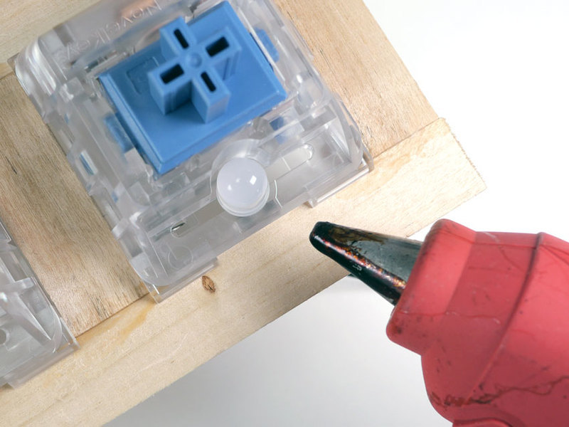
Insert each LED into the LED slot on its respective switch. Use a small amount of hot glue to secure it in place.
Solder Switches
You can use solid core or stranded wire to make connections between the switches and the Circuit Playground. I used solid core to avoid having to twist and tin any wire leads.

To make soldering our wires easier, apply a small amount of solder to each of the switch leads - just be sure not to heat the lead for more than a second or two.

Strip the ends of the black LED wires and wrap them around their respective switch's silver terminal. Cut and strip the ends from two additional pieces of black wire and use them to connect each of the switch's silver terminals as seen above.

Cut and strip the ends from another piece of longer black wire and wrap it around switch 1's silver terminal. Cut three pieces of colored wire and wrap them around each switch's copper terminal.
Once all the pieces are in place, solder them securely to the terminals.
|
|


Mount the Circuit Playground to the front of the frame using velcro or double-sided tape. This will keep it stable while we solder the final connections.

Take the black wire from switch 1's silver terminal and wrap its free end around the Circuit Playground's GND terminal. Connect the remaining switch and LED wires to the Circuit Playground using the connections list at the top of this page.

Once you're sure all connections are correct, solder them to each terminal on the Circuit Playground.


