NeoPixel LED Jewelry

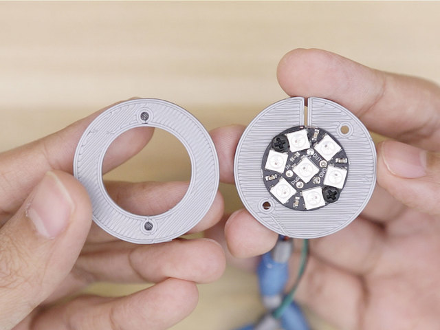
In this guide, we'll build a Legend of Zelda themed pendant. This wearable necklace features the Sheikah symbol and glows nicely making a chic accessory. The parts are 3D printed and snap fit together. Illuminating the pendant is a NeoPixel Jewel which features 7 smart RGB LEDs. Driving the NeoPixels is an Adafruit GEMMA M0, which runs the CircuitPython code base. So, do you want to forge one yourself? Let's get started!

Remix, remake or whatever

If you've made it past the thumbnail, you're probably interested in The Legend of Zelda. But if Zelda isn't your cup o' tea, it's totally possible to re-skin and theme this as whatever you want. Maybe you want to make this as a gift for a friend who's into some other Sci-Fi / fantasy stuff. Maybe they like sports. Or maybe you're into cosplay and need a specific theme. This type of project could potentially sell at craft fairs, make a great listing on your Etsy store or just look good displayed at an art gallery.

Getting 3D Printed Parts

If you don't have a 3D printer laying around, you don't necessarily need to own one. There's lots of ways to obtain the 3D printed parts. The easiest is to send the 3D files to 3DHubs.com and have a local maker 3D print and ship the parts to you. Another option is to search your area for a maker/hacker space or even a library, as some of them have 3D printers now. Either way, there's lots of relatively affordable 3D printers on the market today, some even as low as $150! 

Project Expectations

Although this project may look easy enough to build, it does require a bit of some finesse and craftsmanship. To fit everything into a nice little package requires shortening a lipo battery cable. Rewiring lithium polymer batteries should only be done by confident and experienced makers. So if you're planning this to be your first time electronics project, you may want to consider a more plug and play friendly project. Just be mindful and use common sense :-)

Prerequisite Guides

If your new to electronics and working with micro-controllers NeoPixel LEDs, I suggest you walk through the following guides to get basics of wiring and soldering. The following guides will walk you through setting up the parts and libraries.

Parts & Components

You'll need just a couple a parts to build this project. The GEMMA M0, NeoPixel Jewel and battery are relatively inexpensive, so you don't have to break the bank if you want to make more than one.

1 x GEMMA M0
Adafruit GEMMA M0 - Miniature wearable electronic platform
1 x NeoPixel Jewel
NeoPixel Jewel - 7 x 5050 RGB LED with Integrated Drivers
1 x JST Cable Set
2-pin JST SM plug + receptacle
1 x 150mAh Battery
Lithium Ion Polymer Battery - 3.7v 150mAh
1 x Nylon Screws/Nuts
Black Nylon Screw and Stand-off Set – M2.5 Thread
1 x Kapton Tape
High Temperature Polyimide Tape - 1cm wide x 33 meter roll

Cool Tools!

These things really do help make building the project smoothly. You don't need them all of them, but I recommend them.

1 x Wire Strippers
Hakko Professsional Quality 20-30 AWG Wire Strippers - CSP-30-1
1 x Wire Cutters
Flush diagonal cutters - CHP170
1 x Soldering Iron
Adjustable 30W 110V soldering iron - XY-258 110V
1 x Panavise
Panavise Jr. - PV-201
1 x Helping Third Hands
Helping Third Hand Magnifier W/Magnifying Glass Tool - MZ101
1 x 30AWG Wire
Silicone Cover Stranded-Core Wire - 30AWG in Various Colors
1 x Solder Wire
Solder Spool - 1/4 lb SAC305 RoHS lead-free / 0.031" rosin-core - 0.25 lb / 100 g
1 x Heat Shrink Tubing
Multi-Colored Heat Shrink Pack - 3/32" + 1/8" + 3/16" Diameters
1 x Mounting Putty Tack
Loctite Fun-Tak Mounting Putty 2-Ounce

3D Printed Parts

The largest part is this assembly is about ~50mm in diameter. These are fairly small parts so they should be able to fit on even the smallest of 3D printers. The parts are simple and doesn't require any support material. I suggest using standard PLA filament for these parts, as thats the most common and forgiving material. 

Parts Assembly

The parts are designed to either snap fit together or secured with machine screws. The pendant is composed of five layers that house the NeoPixel Jewel and feature the sheikah symbol and patterns.  The cylindrical enclosure houses the battery and GEMMA M0.

3D Printing 2-Colors

The main pedant (Sheikah symbol) and outer bezel are 3D printed in two different colors. A 3D printer with a dual extrusion toolhead isn't required to achieve these parts. Instead, we can 3D print two colors by using a special pause option in our slicing software. Basically, we print the part in one color, pause the print at a specific layer, then change the filament, and resume printing. This "stacking" method is quite easy to achieve using slicing software like CURA and Simplify3D.

CURA 2.X Post Processing Plugin

The CURA slicing software is most commonly used, and it's free. To achieve 2-color 3D printing, you'll have to enable a (built-in) plugin. Under the top menu, goto Extensions > Post Processing > Modify GCODE > Add Script > Pause at Height. Follow the notes below for getting the various layer heights for the specific colored features.

Simplify 3D Layer Mods

In simplify 3D, there's a different approach. Instead of pausing in the middle of a print job, we separate the slice into two different GCODE files. In the Process Settings, under the Advanced tab is the Layer Modifications section. Here, we can set when to start and stop the print job. Follow the notes before for getting the various layer height for the specific colored features.

The Bezel Ring

  • 0-1mm for the base using black colored filament
  • 1-2mm for the curvy features using gray colored filament

The Sheikah Pendant

  • 0-3mm for the base using translucent or white filament
  • 3-4mm for the sheikah symbol using black filament

3D Printed Beads

The bare wires felt a bit underdressed so I made some simple beads to cover them up. Using different shapes and colored filaments, I formed a pattern that complements the pendant. You could easily buy some beads from a local craft store or even make your own with seeds (popcorn necklace anyone?) or any material, really – They don't need to be 3D printed! 

3D Files and Modifications

The parts were designed in Autodesk Fusion 360. If you're interested in modifying the parts, you can download the source file. If you're using different 3D modeling software, you can save it out as a STEP, IGS, OBJ and other file formats. The STLs can be downloaded "as is" from the repo sites listed below.

Parts for GEMMA M0

  • gemma-actuator.stl
  • gemma-case.stl
  • gemma-cover.stl

Parts for NeoPixel Jewel

  • jewel-bezel.stl
  • jewel-cover.stl
  • jewel-mount.stl

Parts for Sheikah Pendant

  • ring-base.stl
  • ring-traces.stl
  • ring-merged.stl
  • sheikah-stone.stl
  • sheikah-stone-a.stl
  • sheikah-stone-b.stl

Case for GEMMA M0

If you're looking to use the enclosure to house your GEMMA M0, you can download just the case parts. The case is a sub-assembly and available as a stand-alone download.

Circuit Diagram

Use the diagram above to reference the wired connections. The length of wires are not exact, this is just a visual representation of the circuit. The wiring in this project forms a sort of necklace. One side of the lace features a clasp. A male/female JST plug + receptacle cable is wired in between the GEMMA M0 and NeoPixel Jewel – This acts as the clasp. The JST cables are wired to the voltage and ground connections. Data in and a second ground connection make the other side of the necklace.

Wired Connections

The labeling on the pins in this diagram are a bit hard to see, so here's a list that breaks down each connection.

  •  Vout from GEMMA M0 to PWR on NeoPixel Jewel
  • GND from GEMMA M0 to GND on NeoPixel Jewel
  • D2 from GEMMA M0 to Data In on NeoPixel Jewel
  • GND from GEMMA M0 to GND on NeoPixel Jewel

Using CircuitPython with GEMMA M0

The Adafruit GEMMA M0 ships with CircuitPython, making this a plug & play experience. When you plug in a microUSB cable, the board shows up as a USB storage device on your computer. In the CIRCUITPY disk drive, you'll see editable files which contain sample code and libraries. It's pretty awesome!

Upload The Code

The Adafruit GEMMA M0 already has all the libraries we need to control NeoPixel LEDs. So there's no need to install the drivers, software IDE, board profiles, or libraries. Any computer that can use a USB drives can modify code.

In the CIRCUITPY root directory, open the main.py file in a text editing program. Copy and paste the code below into that text document. Save the file and close it. The GEMMA M0 will automatically reboot and run the code. No upload button (say whaaat?!).

Using TextEdit on Mac OS

If you're using this text editing app, I suggest you disable the Spelling and Grammar features to avoid "auto-correcting" any code. You'll want to turn this off before modifying any of the code. You can do so by right-clicking in the text document and unchecking the spelling & grammar options. These are normally enabled by default.

import board
import neopixel

pixpin = board.D2
numpix = 7

pixels = neopixel.NeoPixel(pixpin, numpix, brightness=.3)

pixels[0] = (0,  50, 255)
pixels[1] = (60, 0, 0)
pixels[2] = (60, 0, 0)
pixels[3] = (60, 0, 0)
pixels[4] = (60, 0, 0)
pixels[5] = (60, 0, 0)
pixels[6] = (60, 0, 0)

pixels.write()

CircuitPython NeoPixel Library

Want some more animation from the NeoPixel LEDs? There's a few demo's available that you may find more suitable for your project. Rainbow cycle pattern and color wipes sample code can be found in the Adafruit GEMMA M0 learning guide. If you're a programmer and want to write your own code, the circuitPython NeoPixel library documentation can be found in the Adafruit Github Repository.

Rainbow Cycle

The infamous rainbow cycle displays the NeoPixel like a vibrant rotating color wheel. The arrangement of the NeoPixels in the NeoPixel Jewel make the animation appear somewhat like the "beachball" loading curser in Mac OS.

# Gemma IO demo - NeoPixel

from digitalio import *
from board import *
import neopixel
import time

pixpin = D2
numpix = 7

led = DigitalInOut(D13)
led.direction = Direction.OUTPUT

strip = neopixel.NeoPixel(pixpin, numpix, brightness=0.3)


def wheel(pos):
    # Input a value 0 to 255 to get a color value.
    # The colours are a transition r - g - b - back to r.
    if (pos < 0):
        return [0, 0, 0]
    if (pos > 255):
        return [0, 0, 0]
    if (pos < 85):
        return [int(pos * 3), int(255 - (pos*3)), 0]
    elif (pos < 170):
        pos -= 85
        return [int(255 - pos*3), 0, int(pos*3)]
    else:
        pos -= 170
        return [0, int(pos*3), int(255 - pos*3)]

def rainbow_cycle(wait):
    for j in range(255):
        for i in range(len(strip)):
            idx = int ((i * 256 / len(strip)) + j)
            strip[i] = wheel(idx & 255)
        strip.write()
        time.sleep(wait)

while True:
    rainbow_cycle(0.001)

Connector Clasps

These JST cables are handy for making quick connections. They're pretty solid and lock together nicely. The latch keeps the cable from coming apart easily. In this project, we'll use them to as a clasp for the necklace. 

Shorten Cables

The cable set is fairy long, about 16cm long. You have the optional to use the full length of the cable, if you'd like. I'm my build, I cut them short so that I could hook up 30AWG wire, which is thinner and a bit more flexible. I measure both ends to be about 35mm in length. Admittedly, I trimmed them down shorter near the end of the build to adjust the overall length of the necklace.

Prep JST Wires

Either way, you should strip the ends of the wires using wire strippers and tin the tips using a bit of solder – This will fuse all of the strands of wire preventing them from fraying. A pair of third helping hands can hold the cable steady and in place while soldering. 

Measure Wires

We'll need to measure and cut some pieces of wire to form the necklace. I used four different colored 30AWG wires to tell the connections apart. Each wire will be slightly a different length. Depending on your size preference, you'll need to come up with your lengths. Here's a list of the wires lengths I used in my build.

  • 33cm GND (blue) JST connector & power
  • 30cm GND NeoPixel Jewel to GEMMA M0 (black)
  • 31cm Data in NeoPixel Jewel to GEMMA M0

Wire Stripping

A self adjusting wire stripper can speed things up. This thing can eat through a few wires at a time, which is a lot faster than having to strip each one! We'll want to remove only a bit of insulation from each wire. Getting ready to tin these up.

Tinning Wires

Adding a bit of solder to the exposed wire will fuse all those strands of wire making it easy for them to stick. A pair of third helping hands can hold up the wires and keep them steady while soldering. Be sure to clean and tin the tip of the soldering iron before use!

Wiring NeoPixel Jewel

The wires are soldered from the back of the PCB. First, I tinned the four pins with a bit of solder. The colors follow common wire connections, red for power, black and blue for ground and green for data. I used a panavise jr. to grip the PCB and hold it steady while I soldered them in.  

Thread Beads

With the wires attached to the NeoPixel jewel, you can start adding beads to the wires, making two sets. One lace contains power and ground, while the other is data and the second ground. I meticulously threaded each bead through these wires. Consider the order and placement of the beads for a desired pattern. This is an optional step, so feel free to improvise and use your own materials. Perhaps some fabric sheathing or leather wrapping would work here?

Power and Ground

The voltage and ground wires are wired to the male JST connector. You can follow the same polarity as shown in the photo. The wires on the connector are a single color, but one of the wires has a gray marking on the insulation. You can use that as an indicator to tell the connections apart. Don't forget to add pieces of heat shrink tubing to insulate the exposed the connections.

Thread Beads (Continued)

Proceed to add beads to the second set of wires, the Data In and second ground. I follow the same pattern as the first set for consistency but you can make it asymmetrical if you'd like. The beads can slip out of the wires here, so be sure to temporarily tie them off. Next up, we'll hook up the wires to the Adafruit GEMMA M0.

Double Grounds

This project uses four wired connections even though we really only need three. I did this mainly for consistency so each side of the necklace is two wires. The NeoPixel Jewel features two grounds, so that works great here. I started by securing the GEMMA M0 to panavise jr and then attaching the ground wire. Then, I attached one end of the female JST connector to the ground (GND) pin and the other to voltage out (Vout). Be sure the polarity of the JST connectors are matching.

Voltage Out

Here I'm soldering the second wire from the JST cable to the voltage out pin. I made sure to tin the pins with a bit of solder, first. Notice the placement of the wires – This will make it a bit easier to lay out the necklace when mounting the GEMMA M0 to the enclosure.

NeoPixel Data to GEMMA M0

Lastly, we'll hook up the green data wire to pin D2 on the GEMMA M0. I ended up rewiring this so the connections are on are the opposite ends of each other. This allows the wires to feel more like a necklace. I have the GEMMA M0 secured to third helping hands so the connections can be seen more clearly. 

Danger! Rewiring battery cables is dangerous and potentially hazardous if not done carefully. Take precautions before proceeding, and never touch both black and red wires together with a soldering iron or by cutting

Battery Cable

The battery cable is of decent length for most projects. Unfortunately, we need to cram things into very tight spaces. The stock cable is just too long to fit into the 3D printed case. So we'll desolder the cable from the battery, trim the wire short and rewire it back to the battery. 

Rewiring Battery Cable

I started by carefully removing the layer of kapton tape that's over the voltage and ground pads on the battery. You can also peel back the tape if you'd like to preserve it. I added a fresh piece of kapton tape back over it but if you don't have any, go with the ladder. I secured the battery to my work surface using blue mount tack. Using the tip of the iron, I carefully heated up one pad (not both at the same time!) and slowly pulled the wire away. Then, repeated that process for the second wire. With the cable now free, I cut the wire down to 35mm in length. Strip and tin the two wires. I attached them back to the battery. Follow the + and  labeling on the battery for the voltage and ground connections. The cable is oriented to accommodate for the enclosure.

Kapton Tape

If you don't have any kapton tape on hand, I suggest getting some as they can be handy for future projects. I normally use it to insulate exposed pads on the bottom of PCBs. This helps prevent things from accidentally touching and shorting out. This stuff also handles high temperatures. It's used a lot in different applications like aircrafts, spacecrafts, and x-rays. You'll find this stuff  in electronic manufacturing and 3D printing.

Seal Exposed Wire

Make sure to double check your wiring and ensure the solder joints are solid.

Connect Battery

Now we can plug in the battery to the GEMMA M0. Double check the polarity and make sure the connections are routing correctly – positive to positive, negative to negative. The GEMMA M0 has + and – symbols near the male JST connector. 

Battery Position

The battery cable folds over and fits underneath the GEMMA M0. Notice the wires and solder pads are facing away from the PCB. The 150mAh battery is just the right size to fit under the GEMMA M0. This little package is now ready to install into the enclosure. 

Case for GEMMA

We'll need two M2.5 or M3 (6mm long) machine screws to secure the GEMMA M0 to the 3D printed enclosure. You can use the nylon screw set from the shop or source your own. The nylon plastic screws are less likely to short anything out.

Install GEMMA M0

Place the GEMMA M0 and battery into the 3D printed case with the battery fitting in between the two standoffs. The microUSB port on the GEMMA M0 should be facing the cutout in the case. You'll have to adjust the PCB so the holes on the GEMMA M0 line up with the two standoffs. The case has slits on each side to accommodate for the wiring.

Secure GEMMA M0

Insert and fasten the two machine screws through the top of the GEMMA M0. Make sure the battery is not being punctured by the screw threads. You may want to hold the GEMMA M0 down and keep it steady while fastening.

GEMMA Cover Switch

Thoroughly inspect the GEMMA M0 and make sure it's installed correctly, with the PCB being flush with the standoffs. MicroUSB facing the cutout. Wiring neatly placed through the slits on the side. With the GEMMA M0 now installed to the case, we can get the switch extension and cover.

Install Switch Extension

This little switch extension piece fits on top of the switch actuator and basically allows access to it. It has a little hole on the bottom that fits over the on-board switch. 

Install GEMMA Cover

With the switch extension installed, place the cover over the case and orient them so the holes line up with the cutouts. Firmly press down on the cover to snap it into the case. The JST is exposed to make this as slim as possible. 

Mount for NeoPixel Jewel

Next up, we can work on securing the NeoPixel Jewel to the mounting plate. We'll need two more screws with accompanying hex nuts.

Installing NeoPixel Jewel

Slide the wires from the NeoPixel Jewel through the slit in the mounting plate. Make sure to follow the photo for installing this on the correct side. The wires placed through the center hole in the mounting plate. 

NeoPixel Jewel Mounting Holes

Flip the mounting plate over and rotate until the mounting holes on the NeoPixel Jewel line up with the two holes in the plate. We'll secure the NeoPixel Jewel to the mounting plate with machine screws.

Mount Jewel

Insert and fasten the machine screws from the top of the NeoPixel Jewel while firmly holding the mounting plate flush with the PCB. 

Secure Jewel

To keep the screws in place, we can use hex nuts to secure them in place. Flip the mounting plate back over and twist the nuts onto the screw threads.

Pendant Bezel

An additional bezel piece fits over the mounting plate and allows the pendant to fit on top. These two parts have mounting holes, so they're also secured together with machine screws.

Bezel Mounting Holes

Join the mounting plate and bezel together and rotate until the mounting holes are lined up. Follow the photos for the right placement / orientation.

Mount Bezel

While holding the two parts together, insert and fasten machine screws through the back of the mounting plate, going into the bezel. Fasten the screws until the screw heads are flush with the mounting plate.

Secured Bezel

Inspect the screws and double check to see if everything is tightly fastened. The assembly should resemble the photos, so make sure to reference them.

Jewel Wires

The back of the mounting plate has little notches cut on the sides. This is to allows the wires to fit over them. 

Jewel Pendant Cover

This cover fits over the back of the mounting plate to hide the screws and wiring. It's not 100% necessary but it does keep the screws and wiring from getting caught on pieces of clothing. The cover has a lip with little notches that line up with the ones in the mounting plate. Place the cover over the mounting plate, rotate to line up the notches and firmly press down to snap the cover on.

Install Jewel Cover

The wires are placed through the little notches here. The back of the cover is pretty flat so it can attached to a number of different surfaces.

Install Sheikah Diffuser

Now we can install the Sheikah "stone" over the bezel to finish off the pendant. Make sure to orient the symbol so it's positioned upright with the necklace. 

Secure Pedant

The Sheikah stone press fits into the bezel. You'll need to firmly press the two parts to connect them together.

Install Pendant Ring

The Sheikah stone has some extra thickness to accommodate for the outer ring. This piece also snap fits into place and secured with friction. The outer ring can be oriented however you like. If you find the snap fit pieces are a bit loose, you can permanently fix them in place with adhesives. 

Connecting Lace

Try out the plugging JST connectors together and see if the the wire lengths are to your liking. You can always rewire them if you find it difficult to connect them. I found it much easier to connect these than regular metal claps like the ones found on traditional necklaces. 

Final Adjustments

It's important to try it on, wear it and see how it feels. Is the pendant lopsided? Does it hang too low? With the main assembly setup, you can go back and trim the wires to fit your desired length.

How To Recharge Battery

The 150mAh lithium ion polymer battery can be recharged using an Adafruit Micro Lipo USB charger. Power off the GEMMA M0 before disconnecting the battery. Always grasp and pull the cable from the connector end. Never yank away from the battery.  

You can connect the charger to your computers USB hub or use a 5V power supply to recharge the battery.

Top view of Adafruit Micro Lipo - USB LiIon/LiPoly charger - v1 above a 2-pin JST cable.
Oh so adorable, this is the tiniest little lipo charger, so handy you can keep it any project box! Its also easy to use. Simply plug in the gold plated contacts into any USB port and a...
$5.95
In Stock

This guide was first published on Aug 09, 2017. It was last updated on Aug 09, 2017.