Mini FPV monitor

Build a tiny portable FPV (First-person view) monitor! Great to use as a spectator display at an event or attach to your controller as a backup to goggles. It's rechargeable and has access to the band, channel and brightness controls.

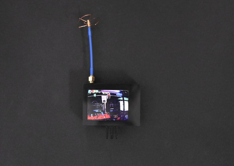
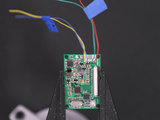
The 2.5" TFT display is powered by a 500mAh lipo battery and a PowerBoost 1000C. The Eachine ER32 VRX AV receiver has 32 channels with frequencies from 5645-5945MHz. Small and low cost with a wide voltage input, it connects to the PowerBoost 1000C.

Tools and Supplies

Electronics

Follow the circuit diagram below and reference the connections for wiring the circuit. Lay out the parts and circuits as shown and then measure each wire with enough slack to solder each component. Lable each set of wires to keep track which wire goes where.

Display Driver

Remove the driver from the display to make soldering easy.
Use a panavise to hold the board in place while soldering.

Solder the Video + (4th pin) to the 3rd pin on the FPV receiver.

Solder Video - (3rd pin) to the 2nd pin on the FPV receiver.

Connect the 1st pin on the display to the 5v on the powerboost.

The 2nd pin on the driver connects to the G pin on the powerboost.

The order of the pins for the Brightness button don't matter.

FPV receiver

The 1st pin on the FPV connects to + on the powerboost.

The 2nd pin on the FPV connects to the - on the powerboost.

The order of the pin for the Band and Channel button don't matter.

Slide Switch

Trim the pins short on the slide switch before soldering wires. 

Connect one of the pins on the slide switch to the EN pin on powerboost.

Connect GND right next to the EN pin on the slide switch.

3D Printed Parts

The FPV Monitor is split into 5 different pieces. The two case parts snap fit together without any screws. 

The 6mm buttons mount into the lid part.  

A riser fits on top of the Powerboost 1000c to elevate the FPV Receiver.

Use #6-32 1/2in screws with nuts to attach the two clamps on controllers.

An M5 x 20 Bolt and acorn nut attaches the case to the clamp parts.

Slicer Settings

To slice the parts, we used Simplify3D. We recommend using the settings below or use them as reference. We 3D printed these parts on a Ultimaker 2+. If you have Simplify3D, you can download our profiles below.

fpvCase.stl

fpv-lid.stl

fpv-pbMount.stl

fpv-clamp1.stl

fpv-clamp2.stl


230c extruder
50mm/s print speed
120mm/s travel speed
0.4mm Nozzle
.44mm Extrusion width


The fpvCase.stl requires supports underneath the hinges.


Lay the fpvCase and fpv-lid flat and add supports underneath the button mounts.


ThefpvCase.stl takes about 3 hours to print.


Thefpv-lid.stl body takes around 1 hour to print.


All of the clamp parts take about 30 mins to print.

Customize The Design

The parts where designed in Autodesk Fusion 360. The design is public and available to download in different formats. If you'd like to use a different CAD software package, you are free to import the files and remix them.

Filament Materials

We recommend using PLA material to reduce wrapping while 3D printing. The parts can be printed in different types of filament, such as ABS, PET or Nylon.

Tolerances

The slots for the buttons may have tight tolerances. Test the tolerances by inserting all of components into each slot. If parts don't fit into the slots, you may need to use a craft knife or filing tool to loosen the area.

Generating Supports

The top body case will need supports underneath the three hinge parts. We can optimize the print by adding supports beneath three hinge parts until it looks like the picture above. 

For the lid, add one support pillars inside each button slot. Make sure the pillars don't touch the side of the walls or the supports can fuse to the walls of the slots.

Removing supports

Use flat pliers to help remove supports. The supports should pull off easy, but take care not to damage the hinge if the supports are fused to the parts.

Use flat pliers to remove the supports inside the button slots.

Use a hobby knife to remove left over filament left over from retraction.

Display driver

To make soldering easy, we'll need to remove the display driver by unlocking the black plastic bar to release the ribbon cable.

Use a panavise to hold the driver while soldering each wire as shown in the circuit diagram.

Brightness button

Solder wires to the two pads as shown above. Careful not to bridge any connections by using a fine tip to solder.

FPV AV Receiver

Carefully tin and solder each wire for composite, composite negative, power, ground, band and channel buttons.

Adding Tac

We couldn't fit standoffs in the compact enclosure, so mounting tac is used to hold the battery and powerboost in place.

Add four dots to the battery and five dots to the powerboost to help them stick to the back of the display. Make sure to add enough tac so they are elevated above the display. 

Mounting buttons

Straighten the pins on the buttons so the can fit through the slots inside the mounts. Use a flat plier bend to the pins.

The tolerances will be tight, use a hobby knife to help loosen the slots.

Tin buttons

Make sure the button pins poke through the slots and tin and solder each button.

Use a panavise to hold the lid while soldering.

Solder Powerboost

Solder each connection to the powerboost as shown in the circuit diagram.


Slide Switch

Shorten the pins on the slide switch with a flush cutters and then tin and solder each wire.

Circuit Complete!


Add tac to the top of the battery to help level the display driver.

Insert into case

Make sure the clean the inside of the case of any filament left over from retraction before fitting the components inside. Carefully angle the display into the case as shown. 

Add tac to the powerboost riser to mount the FPV receiver. 

Antenna

Screw on the antenna to the receiver and tune to the channel the FPV camera is on the test the monitor.

Attaching display to controller

If you plan to use the monitor on the controller,  use #6-32 1/2 inch screws and nuts to attach the clamp parts to the antenna on the controller.

Fly Safe!

Make sure to complete charge the battery before flying! 

This guide was first published on Jun 09, 2016. It was last updated on Mar 08, 2024.