There are 70+ solder points in the complete circuit. We're using 30 gauge wire, which is ideal for working with small solder points.
Measuring + Labeling
We measured and cut all of the wires in their necessary lengths to fit their components. Try to add some leeway to the wires so that they aren't too tight. Label each wire for referencing connections when your ready to solder. We used tiny pieces of painters tape for the labels.NeoPixels + Mic Amp
The 4 neopixels and mic amp will be mounted in the neck frame. We started soldering the neopixels together and into the FLORA, followed by the mic amp. The neck enclosure is designed to fit the neopixels and amp. They should snap right into place. You may need to apply some hot glue to the four neopixels for a really secure fit. The mic amp should have a tight fit to the opening in the neck frame. You can route the wires in between the magnet pillars and frame.LED push buttons
The 6 LED push button need to be mounted into the neck panel. We wired up each LED push button in series with a 220ohm resistor. The 6 LEDs will be powered by the FLORA using a ground and 3.3v(or vbat) pin. Make sure to wire the appropriate connections to positive and negative. You can also route these wires in between the pillars and frame.FLORA
The micro-controller will need to be powered by a battery pack, we are using the 3x AAA battery holder wired to a ground and 3v pin. In our example, the 4 neopixels outputs are connected to D6, 3v and ground. The mic amp out is wired to D9, 3v and a ground. The 6 LEDs in the push buttons will need to get wired together or in groups to a ground.The flora fits in the middle cavity of the base frame. Use a piece of double-sided foam tape to secure the micro-controller.Bluefruit
The bluefruit will be wired to the toggle switch using a ground and vin pin. The positive connections on the arcade and LED buttons will go to pins 0-9, while the negative connections go to ground pins.The negative connections can be wired in groups to the ground pins. The bluefruit should fit nicely in the upper cavity of the base frame. Use a piece of double-sided foam tape to secure the module.Battery & Power Switch
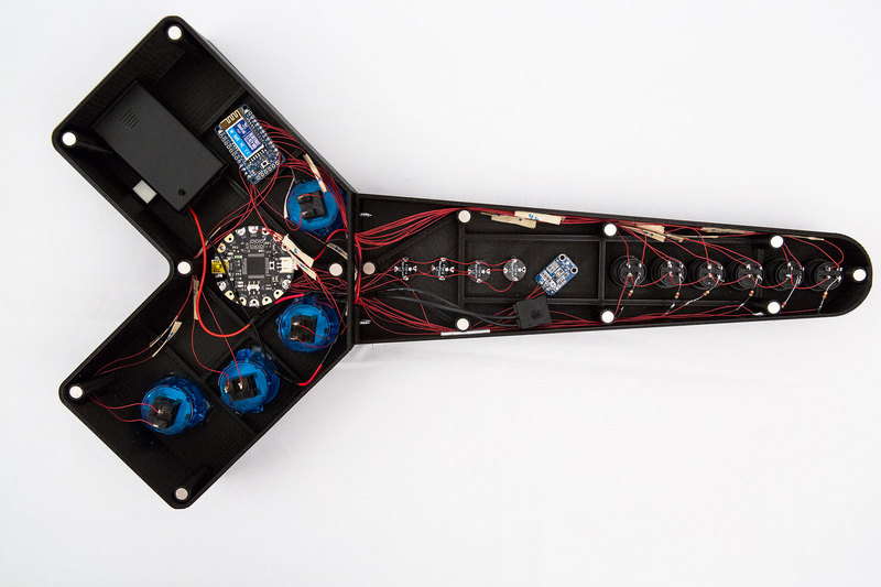
The tactile on/off toggle switch will need to be wired to the 3x AAA battery holder connections. The flora and bluefruit will need to share connections to the toggle switch. On the flora, use a ground and 3v(or vbat) pin. The bluefruit also needs a ground and vin(3v) pin to the switch. Make sure to leave some leeway in the wires so you can remove the back neck cover more easily. The switch component is designed to snap onto the back of the neck cover. The battery pack should fit in the open cavity next to the blue as shawn in the photo below. Use a piece of double-sided foam tape to secure the battery pack .