Bantam Tools Desktop CNC

This little milling machine is great for quickly making prototypes of PCBs and parts. In this guide we'll take a look at the process of milling double-sided PCBs. In this project, we'll make a breadboard adapter for the Adafruit Circuit Playground.

Connecting Things to Circuit Playground Express 

Circuit playground express is a great board with lots of sensors and components. There’s lots of example projects, libraries and code on the Adafruit learning system.

There’s certain projects where you need to connect other components like motors and servos. Using alligator clips is a nice solder-free way to connect things but not always the most robust.

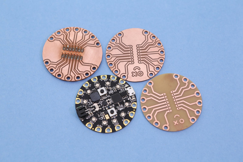
Fabricating a custom PCB adapter with standard 0.1" headers is a great way to attach jumper cables and other connectors Circuit Playground Express.

DIY Perfboard Shields

Dave Astels’s learn guide shows how to make your own breadboard adapter using perf board, standoffs and screws. This allows you to simply plug-in jumper wires making a much more sturdy connection. You can purchase the Circuit Playground Breadboard Biscuit by Dave on Tindie.

A Black woman's manicured hand holds a round microcontroller with lit up LEDs.
Circuit Playground Express is the next step towards a perfect introduction to electronics and programming. We've taken the original Circuit Playground Classic and...
$24.95
In Stock

DIY microUSB Dock

You can 3D print a mini dock for your circuit playground express (or any USB dev board) to display it on your desk. This props it upright allowing you to interact with the on-board components. See our learn guide to build your own.

Tools, hardware and supplies

Here's a list of some handy things I use when cutting some PCBs. 

1 x Bantam Tools Desktop CNC
PCB milling machine
1 x Double sided PCB blanks
FR-1 4" x 5" copper clad boards
1 x Spatula Palette Knife
thin prying tool for removing parts
1 x Double-sided Tape
19mm (3/4in) wide tape for securing
1 x 3m Scotch Brite
Fine Grit Sanding Hand Pad
1 x Squeeze Bottle
Wash Bottle for Alcohol
1 x X-Acto Knife
Precision Knife
14 x M3 x .5 x 4mm screws
Button Head screws
1 x M3 x .5 Hex Nuts
Metric Hex Jam Nuts 1.5mm
1 x Male Headers
Break-away 0.1" male header strip
1 x Gray Blue Silicone Mat
Large Silicone Heat Insulation Pad

Designing in Eagle CAD

I started with downloading the Circuit Playground Express board file from github. Using Autodesk Eagle software, you can open the design and inspect components, traces and the pin layout. From there I referenced the size and positions of the pads. I then created a simple layout with the exact same pin layout and fitted two 1x7 headers in the center of the board. I made sure the spacing between the headers fit a standard breadboard.

If you're new to eagle, I suggest watching a few tutorials on youtube to get familiar with the user interface and features. 

CPX EAGLE Library

Once I laid out the traces on the board, I wanted to create a reusable object of the CPX pin layout so that I could easily create new shields and adapters. As a single object, it's much easier to place it into a new design instead of recreating it each time. The library can be download and added to EAGLE by opening it and adding it to a board design. It features the "device, package and symbol" configuration so it'll properly connect to nets in the schematic layout. 

Feel free to download the library and use it in your projects! 

Design for CNC Milling

Since I plan to mill this on the Bantam tools desktop CNC, theres a few design considerations. I suggest reading through the articles on the Bantam Tool's resource pages. They have some good tips on using vias, ground planes, trace and space widths and a handy design rule check files for eagle.

I tend to design the PCB with a single cutting tool in mind. Using a large tool can make faster cuts which can speed up the machining time. The 1/32in flat end mill is my goto tool that can do all of the traces, holes and board outline if the traces and components are spaced accordingly. In this design, I decided to make the traces thicker than usual (~39mil, 1mm, ~0.039in). This way theres less chance of the trace breaking or getting torn from excessive stress. 

The pads are custom sized circles placed on Layer 17 (the pads layer) with 3mm diameter holes. Circle objects in EAGLE need a width and radius to match the pads on the CPX. A 1mm width and 2.2mm radius fit the pads pretty nicely.

  • Using oblong header pins for the bigger size to make soldering easier.
  • Got creative with lines to make custom emoji face
  • Simplified paths for traces

BantamTools Software 

The software natively supports eagle board files so you can easily add files. First, choose Double-sided FR-1 from the material dropdown. Under the size dropdown, choose the Standard option if you're using the precut material from Bantam Tools. You can optionally set your own if you have custom sized stock.

Double sided tape is the recommend method of securing the material to the spoil board. Under placement, you'll want to adjust the Z-axis input field to match the thickness of the double-sided tape you'll be using. Most double-sided scotch tape is around 0.10mm thick. This option offsets the material away from the spoil board to accommodate for the thickness of the tape.

Under Plans, click Open Files. Browse and select your board file to add it. Once opened, the board will be placed on the spoil board allowing you to rotate around it in 3D. Now we can reposition it and select our milling tools.

Under the placement dropdown of the .brd file, you can set the position of the board anywhere on the material. I suggest offsetting it by 1-2mm on both the X and Y-axis so all of the edges are cut nicely.

Parts to mill, keep "top" selected and deselect the holes and outline options because we'll be doing those on the bottom side of the PCB. It's best to take those for the last operations.

Choose the 1/32in flat end mill for the tools to mill. This will be cutting all of the operations.

By default, the trace depth is 0.15mm ( this is how deep the tool will be cutting into the material). The trace clearances (The spacing between the traces) is set to 0.15mm as well. These options can be changed under the Advanced drop down apart of the board file.

Inspect and Analyze

What you see if what you get. The 3D rendering in Bantam Tools does a great job of showing you how the traces will look once milled. If your design has any intersections or issues they'll be highlighted in red along with a message of how to resolve them.

This is a great way to spot any issues or mistakes that aren't apparent in EAGLE. My process is to check all traces in Bantam Tools, find issues, tweak the traces in EAGLE, then hit the refresh button in Bantam Tools to get instant feedback. Since I'm using a single tool, the 1/32in end mill can be a bit too big to get in tight areas so I needed to rework the traces so they have proper clearances. Being able to see changes update in Bantam Tools very quickly is really nice!

Multiple Copies

You can add as many copies of the same board file as you'd like. Just click Open Files button and select the same .brd file. I was able to fit three boards on one piece of FR-1 board (127mm x 101mm). You'll have to manually type in the X and Y axis of each board to reposition them. Each .brd file contains it's own placement, parts to mill, milling tools and advanced options. Be sure to keep track of each and double check they're consistent.

Setup Fixture

In order to cut precise double-sided boards, we need to install the alignment bracket. This comes with the machine and is secured to the edge of the spoilboard with three screws. I suggest installing the alignment bracket before securing the material. Once installed, in the BantamTools software, click on the Locate button near the fixturing option in the configure sidebar. The software will walk you through the process. It'll prompt you to flip your current milling tool so the blunt end can probe the spoilboard. Once installed it'll proceed to move the toolhead and probe the edges of the alignment bracket and set various offsets. This is how the software maps out where the material is relative to the alignment bracket. This procedure takes about 2-3minutes. Once finished, you can flip the end mill back and click Change under the tool section so the toolhead can probe the reinstalled tool by touching the spoilboard and automatically setting the z-axis offset. Once this is all setup, leave the alignment bracket on until the very end.

Prep Material

Use double-sided scotch tape to secure the FR-1 board to the spoilboard. I use the wide version, which covers more surface area. I use three long strips, evenly placed across the length of the board on the far top, bottom and middle section of the board. Do not overlap the strips or use too much as it will become difficult to remove. Since we're doing double-sided FR-1, doesn't matter which side you choose first. You'll want to wipe down the FR-1 board and the spoilboard with isopropyl alcohol with a paper towel. This will get rid of any debris, grease or finger prints from the surface. 

When you're ready to install the material onto the spoilboard, carefully position the FR-1 board over the lower left corner of the alignment bracket. Square off the edges of the corner so they're both as flush as humanly possible. Then, press down on the material. I like to use a piece of paper towel over the material and apply an even amount of pressure so all of the tape adheres to the spoilboard.

Precut Checklist

Remember, we only want to mill the traces for the top layer and save the holes and outline for the bottom layer. Before milling, run through this checklist to ensure we're properly setup.

  • Check the right milling tool is selected and configured – 1/32 end mill
  • Check the right material profile is setup – Double-sided FR-1 Standard size
  • Check the placement is set to the "left"
  • Check each .brd part is milling only traces and NOT holes and outlines
  • Check tightness of alignment bracket, toolhead and acrylic panels are properly shut

Start Cutting

With everything checked and ready to mill, click the Mill All Visible button. The toolhead will start up and cut around the traces only and work its way through copies, if any. Be sure to watch as the operation takes place. You'll want to be aware and cautious in case something comes loose.

Once the top layer is done, you'll want to use a vacuum to clean out all of the dust and debris from inside the machine. I find it helpful to cycle between the Origin and Loading movements in the Move To section of BantamTools software. These are a quick way to move the toolhead and spoilboard out of the way so you can vacuum under the bed.

Inspect the traces and see if there's any rough edges. I recommend using a scotch brite pad to remove burrs. I spend a few minutes light buffing the surface. This knocks away most of the rough edges and burrs. I normally do this while the PCB is still secured to the spoilboard. 

Remove, Flip and reStick

Next we'll need to remove the PCB from the spoilboard without damaging it. You can use a thin narrow spatula to pry off the PCB but it may lead to bending the FR-1. Use alcohol to soften the adhesive. I like to use a squeeze bottle (or narrow mouth wash bottle) to apply alcohol near the edges of the board. Then use the spatula to fit in between the FR-1 and spoilboard. Getting in between the strips of tape makes for easier removal. Be careful not to mar the bottom copper surface, so take it slow!

Inspect the bottom layer, slight marks can be buffed away with Scotch Brite pad. Proceed if all good. Apply strips of double-stick tape, this time to the top surface with the traces. Flip the board so the traces are facing the spoilboard and line it up with the lower right corner of the alignment bracket. Square the edges so they're as flush as possible. Apply pressure to whole board to fully adhere to the spoilboard.

Cut Bottom Layer

In the software we'll need to turn on the holes and outline for each .brd file. Then, switch to the bottom side of the board by clicking the right alignment button. This will automatically flip each .brd file to the bottom side. Once ready to start cutting, hit the Mill All Visible button. The toolhead will start with the traces, move onto drilling holes and finally cutting the board outline – That takes a few passes to cut. 

Once done you'll want to spend time vacuuming inside the machine using the same method as before. There's a bit more dust from the outlines and holes. Use a scotch brite pad again to buff out any burrs or rough edges.

Follow the process as before to remove the PCB from the spoilboard, again using alcohol and thin spatula. Inspect the top slide and remove any tape and excess FR-1. I recommend doing that over a waste bin to catch and debris and dust. Use scotch bright accordingly!

Clean Up

If the outlines weren't cut all the you can use an x-acto knife to cut out the PCBs. Just follow the contour of the outline and be careful. There might be some excess copper on the edges that can be shaved off using the edge of an x-acto blade. If the holes were no fully drilled out, use a needle to poke them out. You may want to do this over a waste bin, again to catch any dust. Use alcohol to wipe off any grime from the adhesive. Drying with a paper towel is OK but might leave behind paper fibers. Use a scotch brite pad to lightly sand away any frizzy bits. 

DIY Solder Mask

To prevent the copper layers from rusting due to oxidation, you can optionally apply UV curable solder mask to the surfaces. We have a learn guide on how to do just that! There's other options such as coating the surface with protective sprays. 

This guide was first published on May 09, 2018. It was last updated on Mar 08, 2024.