

Overview

This 3D Printed project comes in two different styles. This neoblaster makes a practical ray gun and this ergomonical handle resembles a magnifying glass.
Prerequisite Guides
Tools
Parts & Supplies
Page last edited March 08, 2024
3D Printing
This model is composed of 10 pieces that snap-fit together. Each piece should be printed separately in your favorite colored PLA. The diffuser should be printed in transparent PLA to soften the NeoPixel ring.
| raygun-diffuser.stl raygun-ring.stl raygun-sensor.stl raygun-neck.stl raygun-body.stl raygun-handle-top.stl raygun-handle-btm.stl raygun-handle-lid.stl raygun-cap.stl raygun-cone.stl |
PLA @230 %15 infill 2 shells 0.2 layer height 90/150 speeds |
12 hours? Like a day! Yes, it's for super crazy 3d printer operators. |
Easier to print and assemble, the light handle model is composed of only 4 pieces that snap-fit together.
| flir-handle-btm.stl flir-handle-top.stl flir-handle-light.stl flir-handle-diffuser.stl |
PLA @230 %15 infill 2 shells 0.2 layer height 90/150 speeds |
4-5 hours depending on how soon you switch out the parts! |
Page last edited March 08, 2024
Circuit Diagram
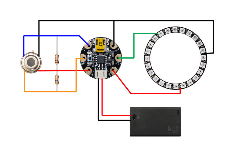
GND > GND NeoPixel Ring
Vout > PWR NeoPixel Ring
GND > Top Right - MLX90614
3V > Bottom Right - MLX90614
D0 > Bottom Left (Include Resistor) - MLX90614
D2 > Top Left (Include Resistor) - MLX90614
JST > 3X AAA Battery Holder
Page last edited March 08, 2024
Arduino Code
// SPDX-FileCopyrightText: 2018 Limor Fried for Adafruit Industries
//
// SPDX-License-Identifier: MIT

/***************************************************
This is a library for the MLX90614 temperature sensor SPECIFICALLY
FOR USE WITH TINYWIREM ON TRINKET/GEMMA

Requires the latest TinyWireM with repeated-start support
https://github.com/adafruit/TinyWireM

NOT FOR REGULAR ARDUINOS! Use the regular Adafruit_MLX90614 for that

  Designed specifically to work with the MLX90614 sensors in the
  adafruit shop
  ----> https://www.adafruit.com/products/1748
  ----> https://www.adafruit.com/products/1749

  These sensors use I2C to communicate, 2 pins are required to
  interface
  Adafruit invests time and resources providing this open source code,
  please support Adafruit and open-source hardware by purchasing
  products from Adafruit!

  Written by Limor Fried/Ladyada for Adafruit in any redistribution
 ****************************************************/

#include <Adafruit_MLX90614.h>
#include <Adafruit_NeoPixel.h>

// change these to adjust the range of temperatures you want to measure
// (these are in Farenheit)
#define COLDTEMP 60
#define HOTTEMP  80


#define PIN 1
Adafruit_NeoPixel strip = Adafruit_NeoPixel(24, PIN, NEO_GRB + NEO_KHZ800);

Adafruit_MLX90614 mlx = Adafruit_MLX90614();

void setup() {
  mlx.begin();
  strip.begin();
  strip.show(); // Initialize all pixels to 'off'
}

void loop() {
  uint8_t red, blue;
  float temp = mlx.readObjectTempF();

  if (temp < COLDTEMP) temp = COLDTEMP;
  if (temp > HOTTEMP) temp = HOTTEMP;

  // map temperature to red/blue color
  // hotter temp -> more red
  red = map(temp, COLDTEMP, HOTTEMP, 0, 255);
  // hotter temp -> less blue
  blue = map(temp, COLDTEMP, HOTTEMP, 255, 0);

  colorWipe(strip.Color(red, 0, blue), 0);

  delay(50); // can adjust this for faster/slower updates
}

// Fill the dots one after the other with a color
void colorWipe(uint32_t c, uint8_t wait) {
  for(uint16_t i=0; i<strip.numPixels(); i++) {
      strip.setPixelColor(i, c);
      strip.show();
      delay(wait);
  }
}
Page last edited March 08, 2024
CircuitPython Code

GEMMA M0 boards can run CircuitPython — a different approach to programming compared to Arduino sketches. In fact, CircuitPython comes factory pre-loaded on GEMMA M0. If you’ve overwritten it with an Arduino sketch, or just want to learn the basics of setting up and using CircuitPython, this is explained in the Adafruit GEMMA M0 guide.
Below is CircuitPython code that works similarly (though not the same) as the Arduino sketch shown on a prior page. To use this, plug the GEMMA M0 into USB…it should show up on your computer as a small flash drive…then edit the file “main.py” with your text editor of choice. Select and copy the code below and paste it into that file, entirely replacing its contents (don’t mix it in with lingering bits of old code). When you save the file, the code should start running almost immediately (if not, see notes at the bottom of this page).
If GEMMA M0 doesn’t show up as a drive, follow the GEMMA M0 guide link above to prepare the board for CircuitPython.
This code requires two additional libraries be installed:
- adafruit_mlx90614
- adafruit_bus_device
- neopixel
If you’ve just reloaded the board with CircuitPython, create the “lib” directory and then download the Adafruit CircuitPython Bundle.
# SPDX-FileCopyrightText: 2018 Mikey Sklar for Adafruit Industries
#
# SPDX-License-Identifier: MIT

#  Designed specifically to work with the MLX90614 sensors in the
#  adafruit shop
#  ----> https://www.adafruit.com/product/1747
#  ----> https://www.adafruit.com/product/1748
#
#  These sensors use I2C to communicate, 2 pins are required to
#  interface Adafruit invests time and resources providing this open
#  source code,
#  please support Adafruit and open-source hardware by purchasing
#  products from Adafruit!

import time
import board
import busio as io
import neopixel
import adafruit_mlx90614

# the mlx90614 must be run at 100k [normal speed]
# i2c default mode is is 400k [full speed]
# the mlx90614 will not appear at the default 400k speed
i2c = io.I2C(board.SCL, board.SDA, frequency=100000)
mlx = adafruit_mlx90614.MLX90614(i2c)

# neopixel setup
num_leds = 24           # how many LEDs
led_pin = board.D1      # which pin the neopixel ring is connected to
strip = neopixel.NeoPixel(led_pin, num_leds, brightness=1)

# change these to adjust the range of temperatures you want to measure
# (these are in Farenheit)
cold_temp = 60
hot_temp = 80

def remapRange(value, leftMin, leftMax, rightMin, rightMax):
    # this remaps a value from original (left) range to new (right) range
    # Figure out how 'wide' each range is
    leftSpan = leftMax - leftMin
    rightSpan = rightMax - rightMin

    # Convert the left range into a 0-1 range (int)
    valueScaled = int(value - leftMin) / int(leftSpan)

    # Convert the 0-1 range into a value in the right range.
    return int(rightMin + (valueScaled * rightSpan))

# Fill the dots one after the other with a color
def colorWipe(color):
    for j in range(len(strip)):
        strip[j] = (color)

while True:
    # get object temperature in celsius
    temp = mlx.object_temperature

    # convert object temperature to fahrenheit
    temp = (temp * 9/5) + 32

    if temp < cold_temp:
        temp = cold_temp

    if temp > hot_temp:
        temp = hot_temp

    # map temperature to red/blue color
    # hotter temp -> more red
    red = remapRange(temp, cold_temp, hot_temp, 0, 255)
    # hotter temp -> less blue
    blue = remapRange(temp, cold_temp, hot_temp, 255, 0)

    colorWipe((red, 0, blue))

    # can adjust this for faster/slower updates
    time.sleep(.05)
Page last edited March 08, 2024
Assembly

This tiny slide switch soldered to a JST extension cable is great way to extend your battery power button. Make sure to use shrink tubing to secure the soldered connections

The resistors are included with the MLX90614. These two resistors can be solder directly on to the GEMMA. Both of them will share the 3V pin of the GEMMA.

And heres what the bare circuit looks like. A bit different then the circuit diagram, right? You will need to ensure the MLX90614 temperature sensor is orientated the correct way in order to solder the connections properly. You can trim the terminals of the sensor. Be sure to use shrink tubing to secure the connections on the sensors.
Page last edited March 08, 2024
The Light Handle

The GEMMA is housed in the flir-handle-btm.stl with the USB port facing the bottom. This allows you to easily reprogram the GEMMA without having to disassemble the handle.
The 3X AAA Battery holder fits in the large space just above the GEMMA. You may need to secure it into place with double sided foam tape or any other plastic-friendly adhesive.
The slide switch adapter is held in place between the two handle pieces. The opening is located in the upper back of the handle parts.
The MLX90614 temperature sensor is housed in the upper front of the handle and also held in place by the two handle parts.

Page last edited March 08, 2024
The Ray Gun

There are 10 pieces to the ray gun. This is a great print if you're really ambitious about 3D Printing. The raygun-neck.stl, raygun-handle-top.stl, and raygun-handle-btm.stl parts require support material to print properly.
Once you have them all printed out, test fit them to see if the tolerance allow for a snap fit. If things are too tight, you can always try sanding down areas to allow assembly. Below is a list of parts that fit to one another.
- raygun-cap.stl > raygun-body.stl
- raygun-neck.stl > raygun-body.stl
- raygun-cone.stl > raygun-neck.stl
- raygun-sensor.stl > raygun-cone.stl
- raygun-ring.stl > raygun-cone.stl
- raygun-handle-top.stl > raygun-handle-btm.stl
- raygun-handle-lid.stl > raygun-handle-top.stl
- raygun-handle-top.stl + raygun-handle-btm.stl > raygun-body.stl
- raygun-diffuser.stl > raygun-ring.stl

The temperature sensor is inserted into the raygun-sensor.stl part with the orientation aligning up with the slit opening for the sensors nub. Use a long thin screw driver to gently press against the sensor, securing into place.

The micro-controller snaps to the inside of the raygun-cap.stl with the USB port facing the large opening for reprogramming without disassembly. The slide switch adapter tightly fits into the opening of the raygun-cap.stl, just above the GEMMA.
The wiring needs to be long enough to run from the raygun-cap.stl to the raygun-body.stl, strung through the raygun-neck.stl and strung through the small hole of the raygun-ring.stl. The wiring should be exposed on the raygun-cone.stl part.

The raygun-handle-top.stl and raygun-handle-btm.stl pieces snap fit together. Both parts have 2mm holes for small screws that will mount the two parts to the raygun-body.stl

The two handle parts and the raygun-body.stl have a large hole, this allows the battery JST wire to run through the parts and is connected to the slide switch adapter that is mounted to the raygun-cap.stl. The raygun-handle-lid.stl part is secured to the raygun-handle-top.stl with 2 small screws.

The fully assembled model is a challenging project but definitely reproducible. Each piece is hollow and optimized for sturdiness.
Page last edited March 08, 2024


