These directions are for the original “Gen 1” Cupcade kit. Later generations of the kit are described in their own sections. You probably don't have one of these unless you have a very old kit!
Let’s refer to this diagram again. The Perma-Proto circuit is done, now we’re placing all the long wires.


Gather up four quick-connects (the unlabeled ones) and squeeze the tips through a piece of heat-shrink tube.


Solder the other end of these four wires to the lower ground bus on the Perma Proto board. The wires enter from the top and are soldered on the underside. Clip any excess wire protruding from the bottom.

Now slide the heat-shrink back down the wires, about 3/4" from the board, and apply heat. Most people simply use a butane lighter for this, but if you have a heat gun that’s even better.
The heat-shrink tube lets these wires rely on each other for support; they’re less likely to break off the board when cramming this into the case later.
The heat-shrink tube lets these wires rely on each other for support; they’re less likely to break off the board when cramming this into the case later.

Now do a similar thing with the four labeled quick-connect wires. Slide a piece of heat-shrink as far along the wires as it will go.

Now slide just one wire part way out, so we can tell it apart from the others at the bare end. Here we pulled the A wire and can identify its tail from the others.

Using the schematic at the top of this page for reference, solder the other end of the wire to the appropriate point on the T-Cobbler. Wire A goes to Pin #21/27
The wires should enter from below the Cobbler and are soldered on the top. This is the opposite of the Perma Proto circuit. Clip away any extra protruding wire after soldering.
The wires should enter from below the Cobbler and are soldered on the top. This is the opposite of the Perma Proto circuit. Clip away any extra protruding wire after soldering.

Repeat with the other three wires, one at a time so you don’t get them mixed up. Slide one wire part way out of the heat-shrink, grab the “tail” and solder in to the correct spot:
A to #21/27
B to #22
¢ to #23
1P to #18
A to #21/27
B to #22
¢ to #23
1P to #18


It’s a very similar game with the U/D/L/R wires: squeeze them all through a piece of heat-shrink tube, then pull out one wire at a time, soldering the tail (unlabeled) end to the appropriate locations on the Cobbler…


Returning to the Perma-Proto for a moment…
Solder the four ribbon jumpers (+, X, Y, –) to the appropriate points on the Perma-Proto circuit, using the diagram at the top of this page for reference.
Since these wires are conjoined, they don’t really need heat-shrink tube, but you can add a piece if it makes you feel better. Remember to slide this on before any soldering.

Add plain wires to the +5V and GND pins on the Cobbler (color-coded if you have them…if not, label these wires to avoid trouble).
These wires get two heat-shrink bits.
Notice also a second piece of heat-shrink has been added to the green joystick wires. But don’t shrink any of these yet.
These wires get two heat-shrink bits.
Notice also a second piece of heat-shrink has been added to the green joystick wires. But don’t shrink any of these yet.

Solder the other end of the power wires to the appropriate positions on the Perma-Proto board, then heat-shrink the tubes near the ends.
The two boards are now permanently connected and will conspire to make your life miserable.
Before making further connections between these two boards or any other parts, plan it out first…make sure you’re not tying knots. As you proceed, turn the boards different ways as necessary to find a smooth path between the two.
Before making further connections between these two boards or any other parts, plan it out first…make sure you’re not tying knots. As you proceed, turn the boards different ways as necessary to find a smooth path between the two.

The four direction wires (U, D, L, R) can now be soldered to the appropriate positions on the Perma-Proto board. Refer to the schematic.
Now you can shrink that second piece of tube on the joystick wires.
See how the two wire bundles aren’t fighting each other or making pretzels? That kind of order is what you’re aiming for.
Now you can shrink that second piece of tube on the joystick wires.
See how the two wire bundles aren’t fighting each other or making pretzels? That kind of order is what you’re aiming for.

That bare copper wire on the audio cable is a problem…it connects to a ground point right next to a +5V line. We must insulate!
Slide a piece of heat-shrink tube a few inches down the cable (surrounding the whole thing, not just the copper wire).
Slide a second piece of heat-shrink tube over just the copper wire (cut one a little longer from your remaining unused tube) and heat it up. This covers most of the wire, but there’s still a tiny gap.
Slide the first piece back up so it covers the gap, apply heat.

Solder the three wires to the proscribed locations on the Perma-Proto circuit.
If you have a headphone cable with red and black and copper wires, treat the black wire as if it were the white wire. The 'raw' copper wire is always the ground wire!
If you have a headphone cable with red and black and copper wires, treat the black wire as if it were the white wire. The 'raw' copper wire is always the ground wire!

Solder two plain wires to the connection points on the speaker.
You can color-code these if you like, but it’s really not vital.
Then add two pieces of heat-shrink tube. Don’t shrink yet!
You can color-code these if you like, but it’s really not vital.
Then add two pieces of heat-shrink tube. Don’t shrink yet!

Solder the opposite end of the wires to the corresponding points on the amplifier circuit, then shrink the tubing near each end.
Soldering’s done!
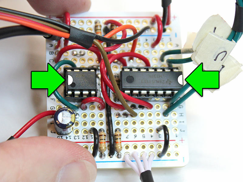
The chips can now be inserted in the sockets. They need to be installed “back to back” — pin 1 (the end of the chip with the little bite missing) is in a different orientation for each: