These directions are for the Gen 1 and 2 Cupcade kits. You probably don't have one of these unless you have a very old kit!
Now we’ll join the speaker and screen parts…

The screen fits into two slots at the bottom of the speaker grille.
Depending which way you’ve installed the screen — horizontal or vertical —one “T-slot” will be located at either the left or the right side.
For a VERTICAL SCREEN: the T-slot should be on the LEFT. If it’s on the right, you’ve got the screen piece upside-down.
For a HORIZONTAL SCREEN: the T-slot should be on the RIGHT. If it’s on the left, the screen piece is upside-down.


Bring the two pieces together and add a #4-40 1/2" screw. This will pass through the speaker frame, the plastic grille piece and into the nut.
Only one of the two speaker/screw holes is used, depending which way the screen is oriented.
Only one of the two speaker/screw holes is used, depending which way the screen is oriented.

Connect the female jumper wires between the joystick and Cupcade board, making sure you get the same sequence (e.g. GND to GND and so forth). If you get these out of sequence, the Pi might not boot!
If your wire bundle has only four wires, you can skip over the Sel pin; it’s not being used here.
If your wire bundle has only four wires, you can skip over the Sel pin; it’s not being used here.


The A and B buttons require an extra step…
First, feed the quick-connect wires through the corresponding slots on the joystick plate.
First, feed the quick-connect wires through the corresponding slots on the joystick plate.
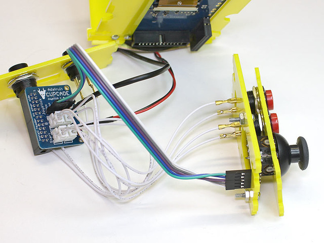
Then plug these into the corresponding sockets on the Cupcade board.
Loosely fit the button support over the joystick support. It’s okay if this flops around for the time being…everything will be held in place later.
Loosely fit the button support over the joystick support. It’s okay if this flops around for the time being…everything will be held in place later.
Look over your wiring before proceeding. Are the wires reasonably well organized, or are they twisted around each other like weeds? If necessary, unplug one wire at a time, untangle it from its neighbors and plug it back into the correct location. This isn’t just a persnickety thing, it’s actually important for fitting everything in the case later!
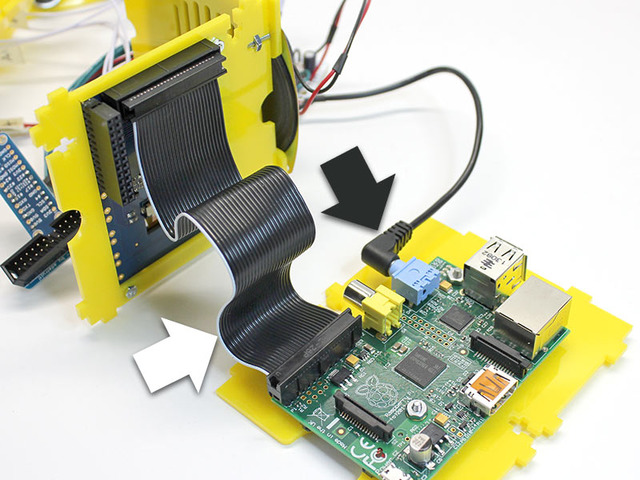
Plug the audio cable into the headphone jack and the ribbon cable to the GPIO header, making sure pin 1 (the white wire) is in the correct place.

The Cupcade board plugs into the back of the PiTFT as it was during our dry run.
Be super extra careful to get the headers correctly aligned. There’s enough wiggle room either direction for it to go one pin out of alignment!
Be super extra careful to get the headers correctly aligned. There’s enough wiggle room either direction for it to go one pin out of alignment!
You can do another dry run at this point if you like…it’s a really good idea. Then shutdown the system (hold credit + start buttons while the game menu is showing).


