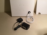
At the end of the last section, we had a blank canvas that can hang on the wall, but with no electronics. The goal for this section is to end up with a canvas that is still mostly blank - allowing for an infinity of further design possibilities - but it will have a running Raspberry Pi system behind the canvas, with one wire bringing in both power and Ethernet.


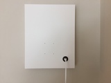
These pictures show the end goal for this section. Behind the canvas is a running Raspberry Pi model 3B with a Power over Ethernet adapter and a USB speaker. The front of the canvas is still primarily blank, except for 4 small nylon screws holding the Raspberry Pi behind the canvas and the circular Ethernet jack.
Next I will describe the parts and tools needed to build the Raspberry Pi system. Before I do that, I want to disclaim that I have some biases when it comes to building Raspberry Pi systems: I prefer Ethernet to WiFi and I like to use a rPi2B, rPi3B or rPi3B+ because of the 4 CPU cores and 1 GB RAM.
But there are a zillion ways to build a CompuCanvas! You could take a more minimal (pure WiFi) approach with a Raspberry Pi Zero W, or go even more minimal and build the system around something like a Circuit Playground Bluefruit. Or you could go bigger with something like a rPi4B. However, changes like that will necessitate other changes to parts and layout that I haven't considered here. So you may want to continue following along with my selection of parts and steps.


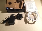
The main picture here shows roughly how I will arrange the rPi system behind the canvas. The second picture shows the key parts (the PyRulers are just shown for scale).
The parts you will need with their Adafruit links are listed just below.
Note that we will use some parts from the nylon screw and standoff set in this section and then use more parts from this set in later sections.
Also, you will need a microSD card for the Raspberry Pi filesystem and you may need an adapter to write a Raspbian image on the microSD card. In case you don't already have these parts, the links are just below.
The parts above will be placed inside the canvas (except for the USB microSD card reader/writer, which is a tool used for programming the microSD memory card). There are some additional parts you will need, to bring power and Ethernet into the canvas.


I like the way that flat Ethernet cables drape from the front of the canvas down to the floor, so I look for cables like the one shown here. This one is seven feet long, but you may need something longer depending on how you place the CompuCanvas in a room.
The other part here is a Power over Ethernet (PoE) injector. This will take power from a wall plug and Ethernet from your home router as input and send out PoE. You don't need the specific TrendNet part shown here, but you do need to use an IEEE 802.3af PoE injector to be compatible with the PoE splitter from the parts list above.
I couldn't find these parts at Adafruit, but they (and similar/compatible parts) are available from many online sources.
There are a few more parts and tools you will need for this section. For most of these, the hardware store is where you will likely find them.


The pictures here show hardware parts that I have used to attach cables to the wood frame of the canvas. I recommend the style of staples shown on the right, if you can find them. These can be pressed in with your thumb such that they will hold temporarily while you layout the parts. Then you can hammer them in more later when your layout is certain.
You will only need 2 or 3 of these staples for this project, so don't buy everything you see here! Just one pack will be enough.


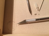
This picture shows some additional tools you will need. The hammer, shown on top, is used for final placement of the cable staples discussed above.
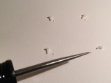
Shown on the lower left here are needles and awls which I use to poke small holes in the canvas. Adafruit sells a needle set, but I have also collected some other needles which are a bit larger. I often start by poking a hole with one of the needles to mark a spot and then use one of the awl tools to make the hole large enough for the nylon screws discussed above.
On the lower right are blades for making straight cuts or large rounded cuts in the canvas. These were already introduced in the previous section of this guide.
Finally, I use a mechanical pencil to mark spots on the canvas for cutting or poking holes. And the PyRulers shown here are not just for scale! You will want a ruler around to measure for some of the layout activities.
Now, with all of these parts and tools assembled we can get down to business. The next few steps will show how I arranged the computer parts behind the canvas and started to mark spots to cut through the canvas.


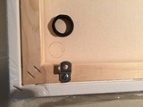

I'm going to start by laying out the panel mount Ethernet cable. The pictures here show how I removed the circular piece that holds the cable from behind and used it to trace out a circle where I will cut through the canvas.
Some other things to note here:
- I used one of the cable staples, placed at an angle, to direct the cable behind the canvas. Don't hammer the staple in yet because we still need to thread the cable through the front. For now just thumb-press it in to mark a spot for it near the center of the canvas.
- Ethernet cables have a notch (as the last picture shows) and this is often oriented down (toward the floor), or it could be on the top, but you probably don't want it in some random orientation, so pay attention to this as you proceed!
- Once you figure out the cable orientation you want, massage/crimp the cable at a right-angle so it will run toward the other side of the canvas.
- This cable is deep enough that it will interact with the foam board. As mentioned in the previous section, I moved the offset clip near this cable transition to the right. This will be shown in more detail in an upcoming section.


Here I am preparing to mark 4 spots to poke holes for mounting the Raspberry Pi to the canvas. The key things to note are:
- In my experience, the actual length of cables can vary a bit from the advertised length. There is no substitute for plugging things together and observing where everything fits (and doesn't). Thus, I have the rPi, the PoE adapter and the Ethernet cable all connected together and pinned to the sides of the frame with staples.
- The first pictures show 3 staples, but the center staple is not present in the last picture. When I got to fitting the USB speaker, I realized that this staple was interfering and should not be used.
- I want the USB speaker to nestle behind the Ethernet cable, as shown in the last picture. I cut this very close! The rPi needs to be about 4.3 centimeters above the frame to fully clear the speaker. Use the speaker, the rPi and a ruler as necessary in the next step to find a positioning that will work.
- Some of these pictures show the nylon screws in the rPi mounting holes. This will be covered in detail in upcoming steps.


Now, hold the Raspberry Pi down in the exact spot where you want it on the canvas and use a mechanical pencil to mark the 4 mounting holes, as shown in the second picture here.
I find that I have to extend the lead from the pencil much more than I would for writing on paper to allow it to reach the canvas. This means it can break easily. But you don't need dark marks for this. Just gently circle the pencil around in each mounting hole and you should get clear enough markings for the next step.


Now it is finally time to make some cuts in the canvas!
First, use a blade type tool to carefully cut around the circle you traced for the Ethernet cable.


Next, use a needle to poke through the center of each of the 4 rPi mounting holes. We will make these holes larger (with the awl) in an upcoming step. For now you just need holes that are visible from the front of the canvas.
The last picture here shows the canvas from the front. Note that the protective plastic is still (mostly) covering the canvas. If you peek ahead to the next step, you'll notice the protective plastic is gone. You know what that means! Yes, go ahead and rip off all the extra plastic to fully reveal your canvas!


Here I have threaded the Ethernet cable through the front of the canvas, and screwed the plastic nut in back to secure it in place.
It was surprisingly difficult to turn the nut around with my fingers, so this step took a while. You may find that a pliers or wrench helps here, or just be patient and gently fiddle it around until it is flush with the canvas.


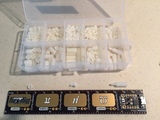
In the next step we will widen the 4 rPi mounting holes and place nylon screws through them. Here you just need to collect the nylon screw parts to use. The first picture shows how the nylon standoffs will be attached to the rPi. The second picture identifies which parts to use from the nylon screw kit, but you need 4 of each:
- 4 of the nuts
- 4 of the medium sized screws
- 4 of the longest standoffs
You can go ahead and attach the standoffs to your rPi as shown in the first picture here.


The 4 nylon screws need to be inserted through the front of the canvas now, so we can attach the rPi in back.
To accomplish this I start by poking a needle through the holes in front and wobbling it around to make the holes a little wider. Then I insert the awl and gently twist and push to make the hole even wider.
Be careful not to make the holes too big! This step can take some time. I gently work on making the holes bigger until they reach the point where they are just wide enough to place the screw and use a screwdriver to twist it all the way in.


The next step is to secure the Raspberry Pi in place. Hold it up so the standoffs align with the screws and then use a screwdriver to attach each one.


Now I am positioning the USB speaker behind the Ethernet cable.
The speaker cable is much longer than is needed here. In the last picture, I've used a yellow twist-tie to attach the extra speaker cable to the Ethernet cable. This helps keep the speaker in place and keeps the extra cabling out of the way.


You will also need to plug in a microSD card with Raspbian, or your preferred OS.
As the pictures here show, the microSD slot is under the rPi on the bottom. It should be inserted with the traces facing toward you.
If you are not sure how to prepare the microSD, don't panic! The next section in this guide will cover the software side of getting your CompuCanvas up and running.


Now we're almost ready to boot this system up! The pictures here show how the PoE injector gets connected in front of the canvas. The yellow Ethernet cable connected to "DATA IN" needs to also be connected to a router or switch on the other end.
Ok, now take a deep breath and admire the pure, pristine beauty of your CompuCanvas enclosure. It's like the Beatles "White Album"! It's like a field covered with fresh snow!
But things are about to get messy. We've been doing physical construction, but now it's time to do software. The next section will cover details from how to setup a microSD card with Raspbian to how to find the CompuCanvas on your network, login and do initial configuration of the system.


