
You may be thinking, "Hey, this TV B GONE looks awesome, but I have a Gemma M0, can I get in on the fun?" Yes you can!
Here's what you'll need to build it:
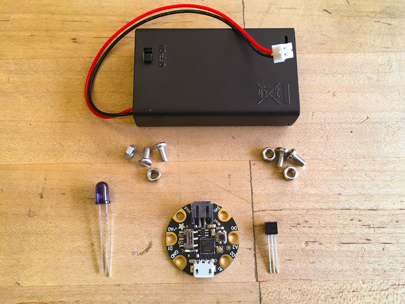
1 x 2N7000 Transistor
4 x M3 x 8mm Screws and Nuts
Build the Gemma M0 TV B GONE
We could connect the IR LED directly to the Gemma M0, but it would have a pretty close range -- in order to boost the power, we'll use a transistor. The transistor will act as an amplifier to boost the current that flows through the LED.
Here's the circuit diagram we'll use.
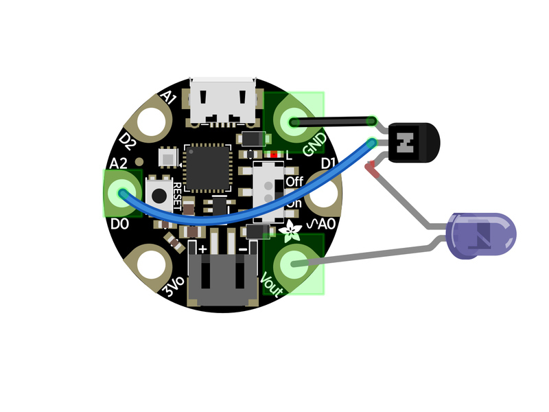
We'll make all of the connections using M3 x 8mm screws and nuts.


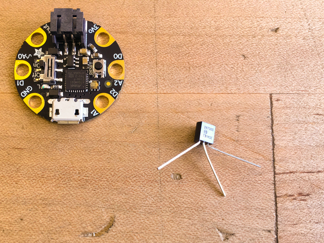


- First, take the transistor and carefully spread the legs as shown
- Bend slightly hooked feet on the source and gate legs
- Screw the source leg in place to GND and the gate leg to A0 as shown
- Note how the drain leg is bent up a bit to connect later to the cathode leg of the IR LED


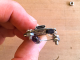


- Next, bend hooks at the ends of both LED legs so they can be connected
- Connect the shorter cathode leg with a screw and nut to the drain leg of the transistor as shown
- Then, connect the longer anode leg connect to the Gemma M0's A0 pad

Power
The Gemma M0 TV B GONE needs power! You can plug in your AAA battery pack, and even affix the Gemma M0 to the case with some double sided foam tape.


Coding with CircuitPython
We'll code the Gemma M0 using CircuitPython. First, follow this guide https://learn.adafruit.com/adafruit-gemma-m0/circuitpython to get started with coding the Gemma M0 in CircuitPython. Install the latest release version of CircuitPython on the board.
You may also want to install the Mu editor https://learn.adafruit.com/adafruit-gemma-m0/installing-mu-editor for your coding needs.
Once you can successfully code in Mu and upload to the board, return here.
The program we'll use is quite small, but we do need to provide a large list of TV off codes as a separate text file on the Gemma M0. In order to save some space, we'll delete some unneeded things from the Gemma M0's CIRCUITPY drive: you can trash the Windows 7 Driver folder, as well as two items from the lib folder: adafruit_hid and neopixel.mpy.


Now, that there's enough space, download the codes file here as codes.txt onto the root of the CIRCUITPY drive.

This is the code for the Gemma M0 TV B GONE. Copy it and then paste it into Mu. Save the file as main.py onto your Gemma M0's CIRCUITPY drive (you can replace the existing main.py file) and it's ready to go!
Temporarily unable to load content:

It's ready for action! Turn it on and watch the TVs go dark!!
You'll see the onboard red LED blink every time a TV code is sent. It can take a some time for it to run through every code in the list, but the time it's done, there's a very good chance it has set some TV sets to sleep!


