After I2C and SPI, the third most popular "bus" protocol used is serial (also sometimes referred to as 'UART'). This is a non-shared two-wire protocol with an RX line, a TX line and a fixed baudrate. The most common devices that use UART are GPS units, MIDI interfaces, fingerprint sensors, thermal printers, and a scattering of sensors.
One thing you'll notice fast is that most Linux computers have minimal UARTs, often only 1 hardware port. And that hardware port may be shared with a console.
There are two ways to connect UART / Serial devices to your DragonBoard. The easy way, and the hard way.
We'll demonstrate wiring up & using an Ultimate GPS with both methods.

The Easy Way - An External USB-Serial Converter
By far the easiest way to add a serial port is to use a USB to serial converter cable or breakout. They're not expensive, and you simply plug it into the USB port. On the other end are wires or pins that provide power, ground, RX, TX and maybe some other control pads or extras.
Here are some options, they have varying chipsets and physical designs but all will do the job. We'll list them in order of recommendation.
The first cable is easy to use and even has little plugs that you can arrange however you like, it contains a CP2102

The CP2104 Friend is low cost, easy to use, but requires a little soldering, it has an '6-pin FTDI compatible' connector on the end, but all pins are broken out the sides.
Both the FTDI friend and cable use classic FTDI chips, these are more expensive than the CP2104 or PL2303 but sometimes people like them!


There is also a GPS module with integrated serial available which works like the GPS breakout connected to the USB to TTL Serial cable.

You can wire up the GPS by connecting the following
- GPS Vin to USB 5V or 3V (red wire on USB console cable)
- GPS Ground to USB Ground (black wire)
- GPS RX to USB TX (green wire)
- GPS TX to USB RX (white wire)

Once the USB adapter is plugged in, you'll need to figure out what the serial port name is. You can figure it out by unplugging-replugging in the USB and then typing dmesg | tail -10 (or just dmesg) and looking for text like this:

At the bottom, you'll see the 'name' of the attached device, in this case its ttyUSB0, that means our serial port device is available at /dev/ttyUSB0
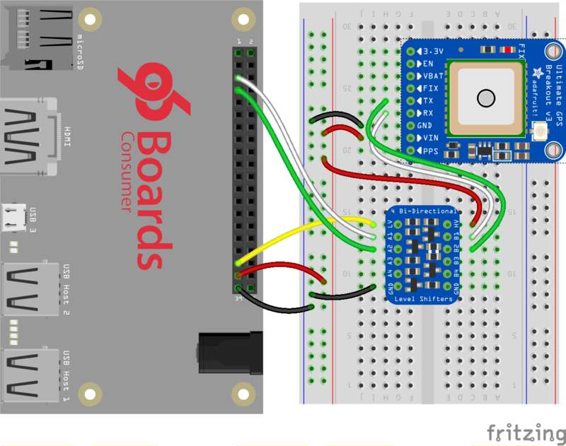
If you don't want to plug in external hardware to the DragonBoard you can use the built in UART on the RX/TX pins. Unlike the Raspberry Pi, the DragonBoard isn't using the RX/TX pins for a console, those are on a different UART peripheral, so you should be good to go!
You can use the built in UART via /dev/ttyMSM1
Wire the GPS as follows:
- Connect the DragonBoard Ground pin to the blue ground rail on the breadboard
- Connect the DragonBoard +5V pin to the red 5V rail on the breadboard.
- Connect the DragonBoard +1.8V pin to the LV pin on the Logic Level Converter
- Connect the HV pin on the Logic Level Converter to the red 5V rail
- Connect the Ground pin on the Logic Level Converter to the blue ground rail on the breadboard
- Connect the Vin pin on the GPS to the red 5V rail on the breadboard
- Connect the Ground pin on the GPS to the blue ground rail on the breadboard
- Connect the B1 pin on the Logic Level Converter to the GPS RX pin
- Connect the B2 pin on the Logic Level Converter to the GPS TX pin
- Connect the DragonBoard UART0 TX to the A1 pin on the Logic Level Converter
- Connect the DragonBoard UART0 RX to the A2 pin on the Logic Level Converter
Install the CircuitPython GPS Library
OK onto the good stuff, you can now install the Adafruit GPS CircuitPython library.
As of this writing, not all libraries are up on PyPI so you may want to search before trying to install. Look for circuitpython and then the driver you want.

(If you don't see it you can open up a github issue on circuitpython to remind us!)
Once you know the name, install it with
sudo pip3 install pyserial adafruit-circuitpython-gps
You'll notice we also installed a dependancy called pyserial. This is a great thing about pip, if you have other required libraries they'll get installed too!
We also recommend an adafruit-blinka update in case we've fixed bugs:
sudo pip3 install --upgrade adafruit_blinka
Run that code!
The finish line is right up ahead. You can now run one of the (many in some cases) example scripts we've written for you.
Check out the examples for your library by visiting the repository for the library and looking in the example folder. In this case, it would be https://github.com/adafruit/Adafruit_CircuitPython_GPS/tree/master/examples
Lets start with the simplest, the echo example:
# SPDX-FileCopyrightText: 2021 ladyada for Adafruit Industries
# SPDX-License-Identifier: MIT

# Simple GPS module demonstration.
# Will print NMEA sentences received from the GPS, great for testing connection
# Uses the GPS to send some commands, then reads directly from the GPS
import time
import board
import busio

import adafruit_gps

# Create a serial connection for the GPS connection using default speed and
# a slightly higher timeout (GPS modules typically update once a second).
# These are the defaults you should use for the GPS FeatherWing.
# For other boards set RX = GPS module TX, and TX = GPS module RX pins.
uart = busio.UART(board.TX, board.RX, baudrate=9600, timeout=10)

# for a computer, use the pyserial library for uart access
# import serial
# uart = serial.Serial("/dev/ttyUSB0", baudrate=9600, timeout=10)

# If using I2C, we'll create an I2C interface to talk to using default pins
# i2c = board.I2C()  # uses board.SCL and board.SDA
# i2c = board.STEMMA_I2C()  # For using the built-in STEMMA QT connector on a microcontroller

# Create a GPS module instance.
gps = adafruit_gps.GPS(uart)  # Use UART/pyserial
# gps = adafruit_gps.GPS_GtopI2C(i2c)  # Use I2C interface

# Initialize the GPS module by changing what data it sends and at what rate.
# These are NMEA extensions for PMTK_314_SET_NMEA_OUTPUT and
# PMTK_220_SET_NMEA_UPDATERATE but you can send anything from here to adjust
# the GPS module behavior:
#   https://cdn-shop.adafruit.com/datasheets/PMTK_A11.pdf

# Turn on the basic GGA and RMC info (what you typically want)
gps.send_command(b"PMTK314,0,1,0,1,0,0,0,0,0,0,0,0,0,0,0,0,0,0,0")
# Turn on just minimum info (RMC only, location):
# gps.send_command(b'PMTK314,0,1,0,0,0,0,0,0,0,0,0,0,0,0,0,0,0,0,0')
# Turn off everything:
# gps.send_command(b'PMTK314,0,0,0,0,0,0,0,0,0,0,0,0,0,0,0,0,0,0,0')
# Tuen on everything (not all of it is parsed!)
# gps.send_command(b'PMTK314,1,1,1,1,1,1,0,0,0,0,0,0,0,0,0,0,0,0,0')

# Set update rate to once a second (1hz) which is what you typically want.
gps.send_command(b"PMTK220,1000")
# Or decrease to once every two seconds by doubling the millisecond value.
# Be sure to also increase your UART timeout above!
# gps.send_command(b'PMTK220,2000')
# You can also speed up the rate, but don't go too fast or else you can lose
# data during parsing.  This would be twice a second (2hz, 500ms delay):
# gps.send_command(b'PMTK220,500')

# Main loop runs forever printing data as it comes in
timestamp = time.monotonic()
while True:
    data = gps.read(32)  # read up to 32 bytes
    # print(data)  # this is a bytearray type

    if data is not None:
        # convert bytearray to string
        data_string = "".join([chr(b) for b in data])
        print(data_string, end="")

    if time.monotonic() - timestamp > 5:
        # every 5 seconds...
        gps.send_command(b"PMTK605")  # request firmware version
        timestamp = time.monotonic()
We'll need to configure this code to work with our UART port name.
- If you're using a USB-to-serial converter, the device name is probably
/dev/ttyUSB0- but checkdmesgto make sure. - If you're using the built-in UART on the DragonBoard, the device name is
/dev/ttyMSM1.
Comment out the lines that reference board.TX, board.RX and busio.uart and uncomment the lines that import serial and define the serial device, like so:
# Define RX and TX pins for the board's serial port connected to the GPS.
# These are the defaults you should use for the GPS FeatherWing.
# For other boards set RX = GPS module TX, and TX = GPS module RX pins.
#RX = board.RX
#TX = board.TX

# Create a serial connection for the GPS connection using default speed and
# a slightly higher timeout (GPS modules typically update once a second).
#uart = busio.UART(TX, RX, baudrate=9600, timeout=3000)

# for a computer, use the pyserial library for uart access
import serial
uart = serial.Serial("/dev/ttyUSB0", baudrate=9600, timeout=3000)
And update the "/dev/ttyUSB0" device name if necessary to match your USB interface.
Whichever method you use, you should see output like this, with $GP "NMEA sentences" - there probably wont be actual location data because you haven't gotten a GPS fix. As long as you see those $GP strings sorta like the below, you've got it working!


