What's a Combadge?
The combadge is a prop from Star Trek (originally appeared in The Next Generation) that is a combination of a badge and communicator. It is used to communicate with Starfleet personnel on-board the ship. When activiated, it makes a destinctive "Chirp" sound.
DIY Combadge
In this tutorial, you'll learn how to turn an Adafruit Circuit Playground into a Star Trek Combadge! When tapped, it'll make the "chirp" sound effect! It won't make any actual phone calls, but it does make a pretty sweet prop for cosplay!
If you do want to make actual phone calls (along with a monthly bill) we made a functional Star Trek Communicator :-)
How Does It Work?
The on-board accelerometer can sense being tapped, triggering a sound to the on-board mini speaker. No soldering is required! All of the components are already on the board. All you need to do is upload the code, plugin a battery, and tap!

Make It How You Want
This tutorial utilizes some special tools like CNC mills and 3D Printers. We understand, those might be hard to come by, but you can totally make the combadge out of any material. Foam, resin, cardboard, whatever you have access to - The point of this tutorial is to learn how to use the Circuit Playground board to make the "guts" of the combadge.

Tools & Supplies
- 3D Printer & Filament
- CNC Milling Machine
- 1/8" Flat-End Mill
- 1/32" Flat-End Mill
- 80º Engraving Bit
- 360 Brass, 6061 Aluminum
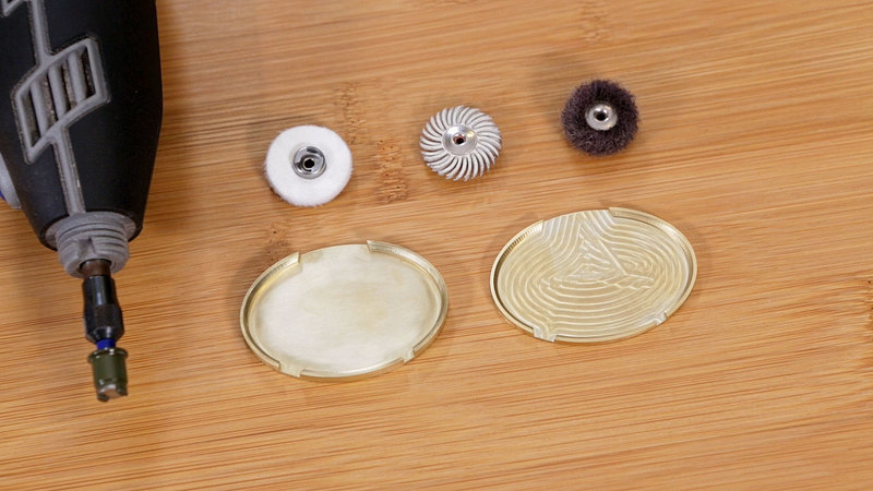
- Dremel Rotary Tool
- Polishing Wheels
- Scotch double-sided tape
- Nitto double-sided tape