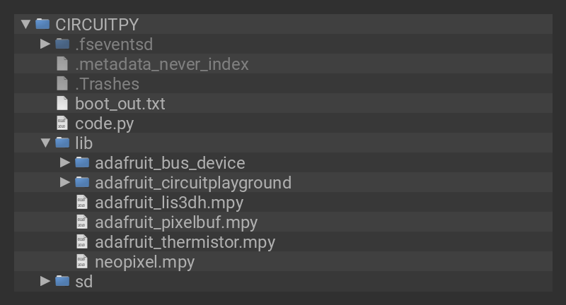
This project makes use of two of the many features available on Circuit Playgrounds; the accelerometer and the NeoPixels. It uses the accelerometer to sense if the bike is braking and then uses the NeoPixels to indicate that the bike is slowing down.

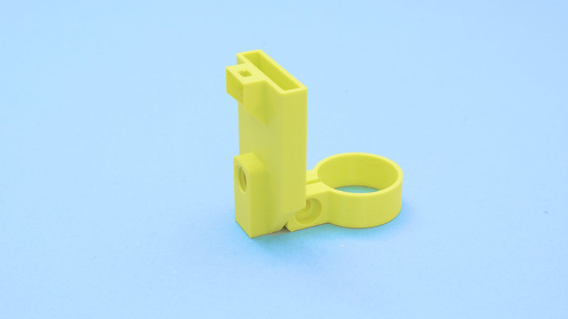
For this project, you will need one Circuit Playground (Bluefruit or Express), one Circuit Playground case, one 500mAh LiPo battery, and one JST extension cable with an on/off switch. You can print a mount that goes on the rails of a bike saddle, and then attach a Circuit Playground and a battery to it.

Two Design Options!

We included two mounting options.

The first design mounts under the seat, while the second design mounts to the seat post.

Both designs include source files to fully customize an exact fit to your bike! 

Parts

shot of a Black woman's neon-green manicured hand holding up a Circuit Playground Bluefruit glowing rainbow LEDs.
Circuit Playground Bluefruit is our third board in the Circuit Playground series, another step towards a perfect introduction to electronics and programming. We've...
$24.95
In Stock
Top down view of a clear acrylic Adafruit Circuit Playground Express or Bluefruit Enclosure.
We've got nice cases for many of our beloved boards, but the Circuit Playground Express and
$4.95
In Stock
Angled shot of a Lithium Ion Polymer Battery 3.7V 500mAh with JST-PH connector.
Lithium-ion polymer (also known as 'lipo' or 'lipoly') batteries are thin, light, and powerful. The output ranges from 4.2V when completely charged to 3.7V. This...
$7.95
In Stock
Top view shot of JST 2-pin Extension Cable with On/Off Switch.
By popular request - we now have a way you can turn on-and-off Lithium Polymer batteries without unplugging them.This PH2 Female/Male JST 2-pin Extension...
$2.95
In Stock

Additional Items

  • One 1/4" 20 nut to secure the two halves of the mount together.
  • One 1/4" 20 X 1/2" bolt to attach the Circuit Playground to the mount.
  • One 1/4" 20 X 1 1/2" to attach to the nut, securing the two halves of the mount.
  • A few 1/4" 20 washers as spacers for the half-inch bolt, since it is slightly too long.
  • A 3D Printer to print the mount for the light.

If you use a Circuit Playground Express, it will work fine, just not quite as well as it would on the faster Bluefruit version.

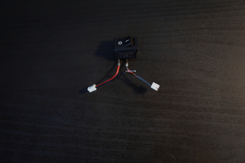
The JST on/off switch isn't necessary, but it is very helpful.

Install or Update CircuitPython

Follow this quick step-by-step to install or update CircuitPython on your Circuit Playground Bluefruit.

Click the link above and download the latest UF2 file

Download and save it to your Desktop (or wherever is handy)

Plug your Circuit Playground Bluefruit into your computer using a known-good data-capable USB cable.

A lot of people end up using charge-only USB cables and it is very frustrating! So make sure you have a USB cable you know is good for data sync.

Double-click the small Reset button in the middle of the CPB (indicated by the red arrow in the image). The ten NeoPixel LEDs will all turn red, and then will all turn green. If they turn all red and stay red, check the USB cable, try another USB port, etc. The little red LED next to the USB connector will pulse red - this is ok!

If double-clicking doesn't work the first time, try again. Sometimes it can take a few tries to get the rhythm right!

(If double-clicking doesn't do it, try a single-click!)

You will see a new disk drive appear called CPLAYBTBOOT.


Drag the adafruit_circuitpython_etc.uf2 file to CPLAYBTBOOT.

The LEDs will turn red. Then, the CPLAYBTBOOT drive will disappear and a new disk drive called CIRCUITPY will appear.

That's it, you're done! :)

Print Files

STL files for 3D printing are oriented to print "as-is" on FDM style machines. Original design source may be downloaded using the link below.

  • Adafruit_Auto_Bike_Light_Bottom.stl
  • Adafruit_Auto_Bike_Light_Top.stl

Slicing

Supports were used on the bottom part, but not on the top.

The parts were sliced using CURA using the slice settings below.

  • PLA filament 210c extruder
  • 0.1mm layer height
  • 30% infill infill
  • 60mm/s print speed

The supports for the bottom half were set to have an 80-degree support overhang angle to avoid them being used in the hole that connects the Circuit Playground, as it wasn't necessary. However, that may depend on the printer being used.

Design source files

The project assembly was designed in TinkerCAD. You can find them here: top part and bottom part.

3D Print Design Option 2

This second design option mounts to the bike seat post and incorporates an integrated slide switch. It uses a M5 screw to secure the mount in place.

Slicing

No Supports are required, we just added 5 top layers to ensure the slide switch roof prints with enough layers.

The parts were sliced using CURA using the slice settings below.

  • PLA filament 210c extruder
  • 0.2mm layer height
  • 20% infill infill
  • 60mm/s print speed
  • 5 Top Layers

Mounting the battery

The battery goes in the slot on the back of the bracket. If you have anything larger than the 500mah LiPo, it will not fit in there. The interior dimensions of the battery holder are 31 x 5mm. The holder is 19mm deep. If you don't have that battery, you can simply take a different LiPo and use adhesive velcro to attach it to the bracket or attach it under the seat with a velcro strap, rubber band, or something else. 

Attaching the mount

Once you've printed the mount, use a 1/4 20 bolt and a 1/4 20 nut to attach it to the saddle rails. I used a nylon lock nut to avoid it shaking loose, but a normal nut should work fine as well.

The mount was designed to fit most saddle rails, so if your saddle has oval rails (saddles with carbon fiber rails often do), it might not work as well, not to mention that you have to be very careful clamping anything to carbon oval rails.

There is a chance that when you attach it to the rails, it won't grip well and will be able to be moved around easily with your hands. In that case, take a tiny bit of rubber from an old inner tube or from a light clamp shim, and put it in-between the 3d printed part and the saddle rails.

Then, take the 1/4" 20 X 1/2" bolt and connect the Circuit Playground to the mount, making sure that the JST battery connection is facing up. You'll probably have to put some washers or other spacers in-between the head of the bolt and the mount. I used a convex brake washer since I've got a bunch of bike parts lying around, but just about any washer that fits will work.

When it's all attached, it should look something like this:

Optional: Making a switch

If you don't have a JST extension cable with a switch built-in, now might be a good time to make one. They're quite simple to make, simply cut and strip one side of any JST extension cable (or even a lipo itself, although this isn't ideal) and solder the two of the ends to a switch. Make sure to tin the wires and the switch contacts beforehand as this makes it much easier. In the example below, I cut both ends since I wanted something rather short.

Design Option 2 Assembly

This second design option mounts to the bike seat post and incorporates an integrated slide switch.

We wired up a slide switch and made a JST adapter so we can easily disconnect it from the battery.

A tripod screw adapter is secured to the mount and features a threaded hole for screwing into.

A quarter twenty screw adapter is used to attach to the clear case.

The slide switch is press fitted into a built in holder behind the battery.

Move the switch to the center and then gently insert at an angle. The two metal sides will press fit between the wall on the case. 

The case attaches into the tripod screw and easily connects to the JST adapter on the slide switch.

The battery is secured to the mount by sliding it into the pocket. 

The slide switch can then plug into the battery.

The mount is designed to flex open so it can fit over the bike frame.

You can clip it right under the seat and slide up and down to adjust the position. 

To secure the mount in place, insert an M5 screw and tightly fastened to a hex nut.

Required libraries

This project does not require any libraries on top of the standard libraries for Circuit Playground boards.

Installing the Project Code

To use with CircuitPython, you need to first install a few libraries, into the lib folder on your CIRCUITPY drive. Then you need to update code.py with the example script.

Thankfully, we can do this in one go. In the example below, click the Download Project Bundle button below to download the necessary libraries and the code.py file in a zip file. Extract the contents of the zip file, open the directory Circuit_Playground_Brake_Light/ and then click on the directory that matches the version of CircuitPython you're using and copy the contents of that directory to your CIRCUITPY drive.

Your CIRCUITPY drive should now look similar to the following image:

CIRCUITPY
# SPDX-FileCopyrightText: 2020 Eva Herrada for Adafruit Industries
#
# SPDX-License-Identifier: MIT

import time
import math
from adafruit_circuitplayground import cp

brightness = 0

# List that holds the last 10 z-axis acceleration values read from the accelerometer.
# Used for the n=10 moving average
last10 = [0, 0, 0, 0, 0, 0, 0, 0, 0, 0]

# List that holds the last 50 z-axis acceleration values read from the accelerometer.
# Used for the n=50 moving average
last50 = [0, 0, 0, 0, 0, 0, 0, 0, 0, 0,
          0, 0, 0, 0, 0, 0, 0, 0, 0, 0,
          0, 0, 0, 0, 0, 0, 0, 0, 0, 0,
          0, 0, 0, 0, 0, 0, 0, 0, 0, 0,
          0, 0, 0, 0, 0, 0, 0, 0, 0, 0]

consecutive_triggers = 0
cp.pixels.fill((255, 0, 0))

light_on = False

while True:
    x, y, z = cp.acceleration

    # moving average n=10, not super smooth, but it substantially lowers the amount of noise
    last10.append(z)
    last10.pop(0)
    avg10 = sum(last10)/10

    # moving average n=50, very smooth
    last50.append(z)
    last50.pop(0)
    avg50 = sum(last50)/50

    # If the difference between the moving average of the last 10 points and the moving average of
    # the last 50 points is greater than 1 m/s^2, this is true
    if avg10 - avg50 > 1:
        if consecutive_triggers > 3: # Is true when avg10-avg50 > 1m/s^2 at least 3 times in a row
            # Detects shake. Due to the very low shake threshold, this alone would have very low
            # specificity. This was mitigated by having it only run when the acceleration
            # difference is greater than 1 m/s^2 at least 3 times in a row.
            if not cp.shake(shake_threshold=10):
                # Set brightness to max, timestamp when it was set to max, and set light_on to true
                cp.pixels.brightness = 1
                start = time.monotonic()
                light_on = True
        consecutive_triggers += 1 # increase it whether or not the light is turned on

    # light_on variable is for short circuiting. Not really necessary, just makes things run faster
    elif not light_on or time.monotonic() - start > 0.4:
        # Sine wave used for the color breathing effect.
        # Max brightness can be adjusted with the coefficient.
        cp.pixels.brightness = abs(math.sin(brightness)) * 0.5
        brightness += 0.05
        consecutive_triggers = 0
        light_on = False

    time.sleep(0.02)

Code Run Through

First, the code imports the required libraries.

import time
import math
from adafruit_circuitplayground import cp

Then, it defines the variables it'll need in the main loop. brightness is used to control the brightness for the breathing effect. last10 becomes a 10-point moving average of the z-axis acceleration, and last50 does the same but with 50 points instead. After that, consecutive_triggers is defined. It is used to make sure the brake light only turns on when the acceleration threshold is met multiple times in a row to prevent false positives. Then, the NeoPixels are set to red. If you'd like to change the color the light uses, just change the RGB values there. light_on is also defined. It's used to bypass an if statement later on in the code to improve performance.

brightness = 0

last10 = [0, 0, 0, 0, 0, 0, 0, 0, 0, 0]

last50 = [0, 0, 0, 0, 0, 0, 0, 0, 0, 0,
          0, 0, 0, 0, 0, 0, 0, 0, 0, 0,
          0, 0, 0, 0, 0, 0, 0, 0, 0, 0,
          0, 0, 0, 0, 0, 0, 0, 0, 0, 0,
          0, 0, 0, 0, 0, 0, 0, 0, 0, 0]

consecutive_triggers = 0
cp.pixels.fill((255, 0, 0))

light_on = False

This next part just starts the while loop and gets the values from the accelerometer every time it runs.

while True:
    x, y, z = cp.acceleration

These next few lines are used to take the moving average. For each moving average, the last value gathered is appended to the list, and then the first is removed. Then, the average of each list is taken. This decreases noise coming from the accelerometer, which makes the brake light function more reliably, and prevents false positives.

last10.append(z)
last10.pop(0)
avg10 = sum(last10)/10

last50.append(z)
last50.pop(0)
avg50 = sum(last50)/50

This block decides whether or not the brake light is to be activated. First, it determines if the Z acceleration has been increasing by comparing the two moving averages. If that increase is in excess of 1 m/s², it will then check to see how many times that has recently happened.

If that has happened 3 or more times in a row, it then goes to check if the accelerometer in the board has detected being shaken. If the accelerometer is detecting being shaken, it won't turn on the light.

If it hasn't been shaken, and the previous conditions have all been met, then it sets the brightness to maximum and makes a timestamp for when that happened. That timestamp will later be compared to the current time. This method was used instead of time.sleep to preserve the validity of the moving averages, as sleeping would keep them from updating.

The variable light_on is then set to true. This will disable the if statement in the next block.

Regardless of what happens, as long as the initial condition (avg10 - avg50 > 1) was satisfied, the variable consecutive_triggers is increased by 1.

if avg10 - avg50 > 1:
    if consecutive_triggers > 3:
        if not cp.shake(shake_threshold=10):
            cp.pixels.brightness = 1
            start = time.monotonic()
            light_on = True
    consecutive_triggers += 1

The first line here is true when light_on is False, or when start subtracted from the current time is greater than 0.4 seconds. light_on uses short-circuiting to only have the second half of the if statement evaluated if light_on is True, which means that the brake light is currently on.

Then, if the statement evaluates to true, the breathing effect will continue. It uses a sine wave to generate the wave-shaped brightness curve. If you want to make it slower, decrease the number brightness is increased by, and if you want to adjust the max brightness, change the coefficient outside of the absolute value function. 

Then, consecutive_triggers is reset and light_on is set to False.

If the condition does not evaluate to True, then the code repeats.

elif not light_on or time.monotonic() - start > 0.4:
    cp.pixels.brightness = abs(math.sin(brightness)) * 0.5
    brightness += 0.05
    consecutive_triggers = 0
    light_on = False

After this, there's a time.sleep. This was added in because when there wasn't one, something wacky happened in the serial console that kept crashing my computer.

time.sleep(0.02)

So, now that you know how the code works, it could be useful to know how it actually behaves.

Normally, it is in the mode where the brightness increases and decreases in a wave-shaped way, creating what I call a 'breathing' effect. 

When the bike starts decelerating, the brake light turns on. This takes about 100-200 ms to happen from the second you start braking. The light can also be triggered by actions such as going over a speed bump. It works best on paved roads or smoother trails. It does not work very well on mountain biking trails and other rough terrains.

From the time the light was last turned on, and this can happen multiple times during a braking event, to when the breathing effect resumes, there are at least 0.4 seconds. This number can be greater than 0.4 since even when the light is on, the code is still checking to see if the bike is still decelerating and will reset the timer if it is.

As far as battery life goes, using the 500 mAh battery, you should probably get around 1.5 hours of usage from it. Because of that, you may want to consider bringing extra batteries for longer rides or attaching a larger battery under the seat using tape or velcro. 

Final thoughts

Now that you've got the light all hooked up and working, you should be ready to go riding with it. Just keep in mind that this light is much more visible to other cyclists than to drivers of cars, so you should still be careful when riding at night. Riding bikes is a lot of fun, and I hope you enjoy building and using this as much as I did.

This guide was first published on Jun 16, 2020. It was last updated on Apr 17, 2024.