
There's no ready-made breakout board for the OV cameras and the Raspberry Pi, so get ready to do some wiring.
This diagram shows the many connections needed. Continue below for a list.

Because the camera has two rows of connections that are 0.100 apart, a standard solderless breadboard doesn't work very well. Use a solderable breadboard or perfboard. If your solderable perfboard has a gap down the middle, you can use an IDC Breakout Helper, but these do not work well with solderless breadboards.
You can also use jumper wires (M-F to go from breadboard to camera, or F-F to go from pico pin header to camera), which is also nice because it gives you some flexibility to orient the camera differently than the LCD.
Power & Ground
- Connect GND of LCD, Pico, and Camera
- Connect 3V3 from Pico to Camera
- Connect 3V3 from Pico to I2C pull-up resistors (×2)
- Connect VSYS from Pico to LCD VIN
LCD Connections
- Connect Pico GP2 to LCD SCK
- Connect Pico GP3 to LCD MOSI
- Connect Pico GP0 to LCD D/C
- Connect Pico GP1 to LCD CS
I2C Connections
- Connect one I2C pull-up resistor to Pico GP8
- Connect the other I2C pull-up resistor to Pico GP9
- Connect Pico GP8 to Camera SDA
- Connect Pico GP9 to Camera SCL
Camera Control Connections
- Connect Pico GP7 to Camera VSYNC
- Connect Pico GP10 to Camera RESET
- Connect Pico GP11 to Camera CLOCK
- Connect Pico GP20 to Camera MCLK
- Connect Pico GP21 to Camera HREF
Camera Data Connections
- Connect Pico GP12 to Camera D0
- Connect Pico GP13 to Camera D1
- Connect Pico GP14 to Camera D2
- Connect Pico GP15 to Camera D3
- Connect Pico GP16 to Camera D4
- Connect Pico GP17 to Camera D5
- Connect Pico GP18 to Camera D6
- Connect Pico GP19 to Camera D7
Make sure you can see the Pico's CIRCUITPY drive and connect to the REPL. Open the REPL and double check that import imagecapture works without showing an error. Then, copy the correct bundle to your device. It will automatically reload and start displaying the image from the camera on the built-in LCD.
For the OV2640 camera
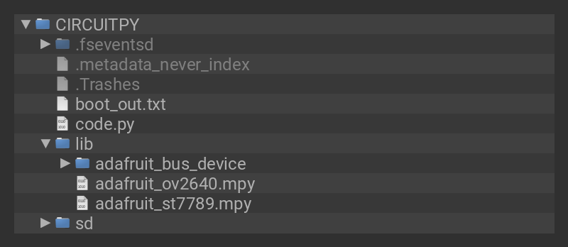
Click the Download Project Bundle button below to download the necessary libraries and the code.py file in a zip file. Extract the contents of the zip file, and copy the entire lib folder and the code.py file to your CIRCUITPY drive.
Your CIRCUITPY drive should resemble the image.
You should have in / of the CIRCUITPY drive:
- code.py
And in the lib folder on your CIRCUITPY drive:
- adafruit_bus_device
- adafruit_ov2640.mpy
- adafruit_st7789.mpy
# SPDX-FileCopyrightText: 2017 Scott Shawcroft, written for Adafruit Industries
# SPDX-FileCopyrightText: Copyright (c) 2021 Jeff Epler for Adafruit Industries
#
# SPDX-License-Identifier: Unlicense

"""
Capture an image from the camera and display it on a supported LCD.
"""

import time
from displayio import (
    Bitmap,
    Group,
    TileGrid,
    FourWire,
    release_displays,
    ColorConverter,
    Colorspace,
)

from adafruit_st7789 import ST7789
import board
import busio
import digitalio
import adafruit_ov2640

release_displays()
# Set up the display (You must customize this block for your display!)
spi = busio.SPI(clock=board.GP2, MOSI=board.GP3)
display_bus = FourWire(spi, command=board.GP0, chip_select=board.GP1, reset=None)
display = ST7789(display_bus, width=320, height=240, rotation=270)
display.auto_refresh = False

# Ensure the camera is shut down, so that it releases the SDA/SCL lines,
# then create the configuration I2C bus

with digitalio.DigitalInOut(board.GP10) as reset:
    reset.switch_to_output(False)
    time.sleep(0.001)
    bus = busio.I2C(board.GP9, board.GP8)

# Set up the camera (you must customize this for your board!)
cam = adafruit_ov2640.OV2640(
    bus,
    data_pins=[
        board.GP12,
        board.GP13,
        board.GP14,
        board.GP15,
        board.GP16,
        board.GP17,
        board.GP18,
        board.GP19,
    ],  # [16]     [org] etc
    clock=board.GP11,  # [15]     [blk]
    vsync=board.GP7,  # [10]     [brn]
    href=board.GP21,  # [27/o14] [red]
    mclk=board.GP20,  # [16/o15]
    shutdown=None,
    reset=board.GP10,
)  # [14]

width = display.width
height = display.height

cam.size = adafruit_ov2640.OV2640_SIZE_QQVGA
# cam.test_pattern = True
bitmap = Bitmap(cam.width, cam.height, 65536)

print(width, height, cam.width, cam.height)
if bitmap is None:
    raise SystemExit("Could not allocate a bitmap")

g = Group(scale=1, x=(width - cam.width) // 2, y=(height - cam.height) // 2)
tg = TileGrid(
    bitmap, pixel_shader=ColorConverter(input_colorspace=Colorspace.BGR565_SWAPPED)
)
g.append(tg)
display.root_group = g

display.auto_refresh = False
while True:
    cam.capture(bitmap)
    bitmap.dirty()
    display.refresh(minimum_frames_per_second=0)
CircuitPython will automatically reload and begin showing the image from the camera on the LCD. If it doesn't, you can open up the REPL to diagnose what went wrong. Double check that you copied all the files from the bundle, and that you have a compatible build of CircuitPython installed, 7.0.0-beta.0 or newer.
For the OV7670 camera
Click the Download Project Bundle button below to download the necessary libraries and the code.py file in a zip file. Extract the contents of the zip file, and copy the entire lib folder and the code.py file to your CIRCUITPY drive.
Your CIRCUITPY drive should resemble the image.
You should have in / of the CIRCUITPY drive:
- code.py
And in the lib folder on your CIRCUITPY drive:
- adafruit_bus_device
- adafruit_ov7670.mpy
- adafruit_st7789.mpy

# SPDX-FileCopyrightText: 2017 Scott Shawcroft, written for Adafruit Industries
# SPDX-FileCopyrightText: Copyright (c) 2021 Jeff Epler for Adafruit Industries
#
# SPDX-License-Identifier: Unlicense

"""
Capture an image from the camera and display it on a supported LCD.
"""

import time
from displayio import (
    Bitmap,
    Group,
    TileGrid,
    FourWire,
    release_displays,
    ColorConverter,
    Colorspace,
)
from adafruit_st7789 import ST7789
import board
import busio
import digitalio
from adafruit_ov7670 import (
    OV7670,
    OV7670_SIZE_DIV1,
    OV7670_SIZE_DIV16,
)

# Set up the display (You must customize this block for your display!)
release_displays()
spi = busio.SPI(clock=board.GP2, MOSI=board.GP3)
display_bus = FourWire(spi, command=board.GP0, chip_select=board.GP1, reset=None)
display = ST7789(display_bus, width=320, height=240, rotation=270)


# Ensure the camera is shut down, so that it releases the SDA/SCL lines,
# then create the configuration I2C bus

with digitalio.DigitalInOut(board.GP10) as reset:
    reset.switch_to_output(False)
    time.sleep(0.001)
    bus = busio.I2C(board.GP9, board.GP8)

# Set up the camera (you must customize this for your board!)
cam = OV7670(
    bus,
    data_pins=[
        board.GP12,
        board.GP13,
        board.GP14,
        board.GP15,
        board.GP16,
        board.GP17,
        board.GP18,
        board.GP19,
    ],  # [16]     [org] etc
    clock=board.GP11,  # [15]     [blk]
    vsync=board.GP7,  # [10]     [brn]
    href=board.GP21,  # [27/o14] [red]
    mclk=board.GP20,  # [16/o15]
    shutdown=None,
    reset=board.GP10,
)  # [14]

width = display.width
height = display.height

# cam.test_pattern = OV7670_TEST_PATTERN_COLOR_BAR

bitmap = None
# Select the biggest size for which we can allocate a bitmap successfully, and
# which is not bigger than the display
for size in range(OV7670_SIZE_DIV1, OV7670_SIZE_DIV16 + 1):
    cam.size = size
    if cam.width > width:
        continue
    if cam.height > height:
        continue
    try:
        bitmap = Bitmap(cam.width, cam.height, 65536)
        break
    except MemoryError:
        continue

print(width, height, cam.width, cam.height)
if bitmap is None:
    raise SystemExit("Could not allocate a bitmap")

g = Group(scale=1, x=(width - cam.width) // 2, y=(height - cam.height) // 2)
tg = TileGrid(
    bitmap, pixel_shader=ColorConverter(input_colorspace=Colorspace.RGB565_SWAPPED)
)
g.append(tg)
display.root_group = g

t0 = time.monotonic_ns()
display.auto_refresh = False
while True:
    cam.capture(bitmap)
    bitmap.dirty()
    display.refresh(minimum_frames_per_second=0)
    t1 = time.monotonic_ns()
    print("fps", 1e9 / (t1 - t0))
    t0 = t1
CircuitPython will automatically reload and begin showing the image from the camera on the LCD. If it doesn't, you can open up the REPL to diagnose what went wrong. Double check that you copied all the files from the bundle, and that you have a compatible build of CircuitPython installed, 7.0.0-beta.0 or newer.
Adapting to other RP2040 boards
By selecting appropriate pins, you can adapt the example to work on other RP2040 boards which are supported by CircuitPython and have enough pins exposed for the connections below:
- mclk, pclk, vsync, href: Free choice of any pin
- reset, shutdown: Free choice of any pin. Can omit one or both, but the initialization sequence is less reliable.
- d0…d7: These 8 pins must be consecutive in the "IO##" ordering, so you could use IO3…IO10, IO9…IO16, etc.


