
PCB Mounting Hardware
Use the following hardware to install on the PCB Mount.
- 4x M2.5 x 6mm FF standoffs
- 4x M2.5 x 4mm long machine screws

Install Standoffs
Insert machine screws through the four mounting holes on the PCB mount. Reference the photo for correct placement and orientation. Fasten the standoffs onto the machine screws.
These standoffs will be used to secure the Raspberry Pi.


Secure PCB Mount to Frame
Place the PCB mount over the tabs on the frame.stl part. Use the following hardware to secure the PCB mount to the frame.stl part.
- 4x M2.5 x 6mm long machine screws
- 4x M2.5 hex nuts

Pi Camera Hardware
Use the following hardware to secure the Pi Camera Module (either V2 or the HQ module)
- 8x M2.5 x 4mm long machine news
- 4x M2.5 x 12mm long FF standoffs

Install Standoffs to Camera
Insert the M2.5 machine screws through the four mounting holes on the raspberry pi camera module PCB. Insert and fasten the standoffs on to the screws. Finger tightened the screws to secure the standoffs.


Secure Camera to PCB Mount
Place the Raspberry Pi camera module over the PCB mount and line up the standoffs with the mounting holes. Reference the photo for correct placement and orientation.
Use 4x M2.5 x 4mm long machine screws to secure the standoffs on the Pi camera module to the PCB mount.

Secure Pi to PCB Mount
Use 4x M2.5 x 4mm long machine screws to secure the Raspberry Pi to the PCB mount. Place the Raspberry Pi over the four standoffs that you installed earlier. These should be facing the opposite direction of the Pi Camera. Insert the screws through the Pi's mounting holes first, then place the PCB over the standoffs.
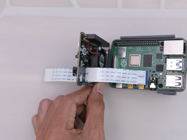


Connect Flex Cable
Insert and install the flex PCB cable on to the camera connector on the Raspberry Pi. Thread the flex PCB cable through the slot on the BrainCraft HAT – Pull the cable all the way through. Then, snap fit the BrainCraft HAT on top of the Raspberry Pi. Firmly press the headers together.

Tripod Hardware
This step is for specifically for the Raspberry Pi Camera Module v2.
The Raspberry Pi HQ Camera has a built-in tripod screw and does not require this step.
Use the following hardware to secure the tripod mounting plate to the back frame.
- 2x M2.5 x 6mm FF standoffs
- 4x M2.5 x 4mm machine screws

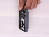
Install Tripod Screw
Install a 3/8 to 1/4-20 screw insert to the tripod plate. Use a 3/8-16 size tapping tool to create better threads in the 3D printed plate. The tripod screw insert can be fastened using a flat head screw driver.


Install Tripod Plate
Insert the M2.5 x 4mm screws through the two holes on the side of the back-frame.stl part. Insert and fasten the 2x M2.5 x 6mm FF standoffs to the thread of the screws – Note the placement of the standoffs. Use 2x M2.5 x 4mm screws to secure the tripod plate to the standoffs.

Install Back Frame
Carefully fit the back-frame.stl part over the BrainCraft HAT and snap fit it onto the frame.stl part. Thoroughly "click" all of the edges together to secure the framing

Connect Flex Cable to Camera
Insert the flex PCB cable into the camera connector on the Raspberry Pi camera module. The blue colored side should be facing away from the camera's image sensor.
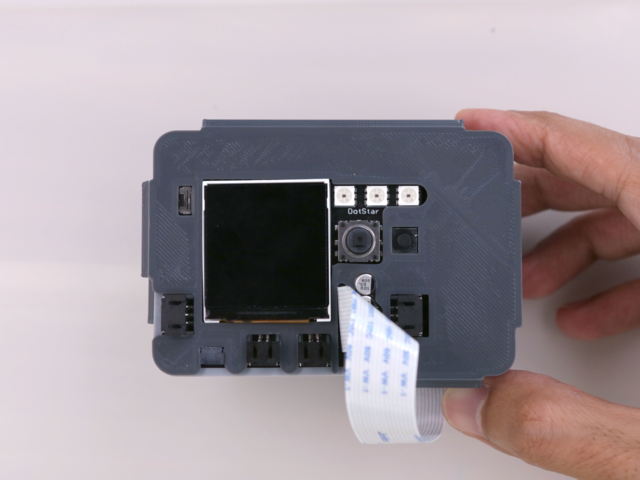
BrainCraft HAT Cover
Place the back-cover.stl over the BrainCraft HAT and orient the cover so matches the display, buttons and ports. Slide the flex PCB cable from the camera over the slit on the back cover. Press all of the edges together to fully secure the cover.


