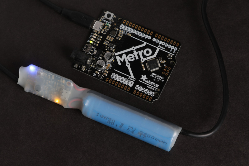
The PowerBoost Chargers are super versatile portable power sources.  The one missing feature is the ability to pass USB data so you can exchange data with your computer while the LiPo battery is charging.  This project turns your PowerBoost Charger into a LiPo Powered USB Data Cable.

The Booster Cable is a relatively easy project.  Once you collect all the components and tools, it should only take an hour or two to assemble.

Required Components:

  • PowerBoost 500 Charger (shown) or PowerBoost 1000 Charger
  • USB Cable  - choose one with a 'B' connector to fit your device
  • LiPo Cell - 2200mAh - or whatever size fits your project best
  • 2 small ‘zip’ ties
  • Electrical tape

Optional Components:

Your enclosure choice will depend on the battery selection.  For this build, we’ll simply use some 3/4”  heat-shrink tubing and a cylindrical battery to make a compact in-line package.

Other options include mint or gum tins or other small project boxes.

Tools:

  • Hobby Knife
  • Wire Cutters
  • Wire Strippers
  • Soldering Iron & supplies

Optional:

  • Hot-air gun (for heat-shrink tubing - if used)

Remove a section of the insulation.  

Pick a spot in the middle of the USB cable and use a sharp knife to cut through the outer insulation only.  Make your cut about the same length as the PowerBoost PCB.  Then peel back the insulation to expose the braided shield.

Separate the wires from the shield

Cut away the insulation and separate the shield wires to expose the wires inside.  If there is a foil wrapper around the wires, remove it.


The Red and Black wires are the Power and Ground wires.  The White and Green wires are the Data wires.

Cut and Strip the Power and Ground Wires

 Cut the power and ground wires.  Strip off about 1/4" of isulation from each side.  Leave the white and green data wires intact.

Solder the 'A' side wires:

These are the inputs to the PowerBoost.

  • Red to USB
  • Black to GND

Solder the 'B' side wires:

These are the outputs from the PowerBoost.

  • Red to 5Vo
  • Black to GND

Insulate the bare wires

Fold a piece of electrical tape over the bare shield wires.  This will prevent any short circuits from the bare wires.

Secure with 'Zip' ties

Fold the insulated shield wires down on the back of the PowerBoost and secure the ends with 3" 'zip' ties and trim the ends.

Test it

Plug in a battery and make sure that everything is working.

Wrap it up!

For the prototype here, we soldered the battery leads directly to the BAT and GND pins.  Then slid the whole thing into a piece of translucent 3/4" heat-shrink tubing for a nice compact in-line package.

This guide was first published on Apr 25, 2016. It was last updated on Apr 25, 2016.