Raspberry Pi Boombox

In this Project we’re using a Raspberry Pi Zero W to make an AirPlay-ready audio player. With shairport sync, you can stream audio from an iOS device to the Raspberry Pi. We think this is a great little airplay speaker project using Raspberry Pi, 3D printing, and electronics.

Portable Airplay Speaker

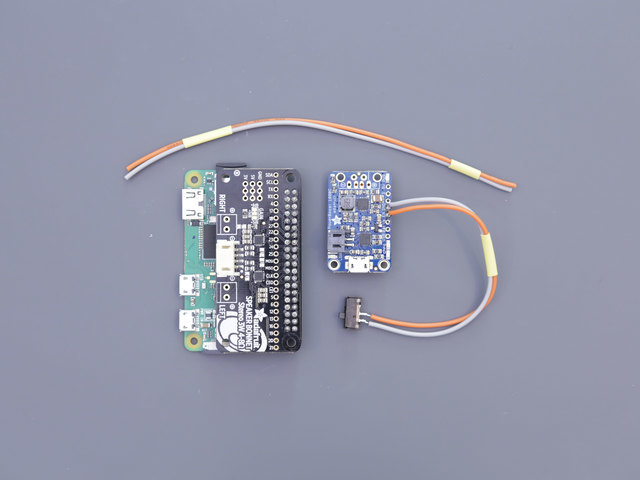
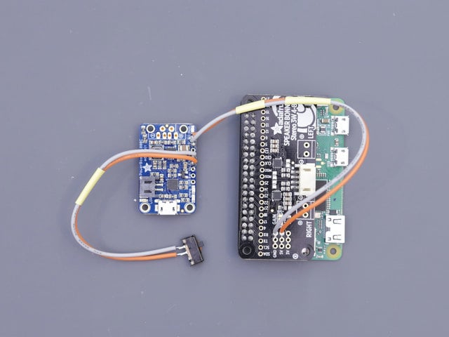
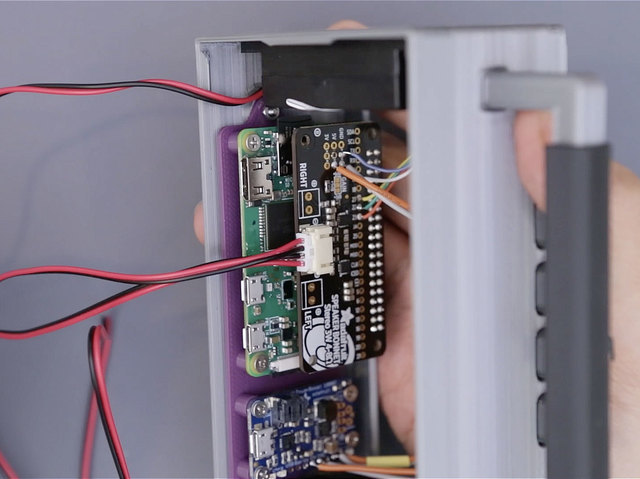
This project features 2x 3W stereo speakers that are hooked up to an Adafruit Speaker Bonnet. This handly little Pi accessory gives your Pi a stereo audio amplifier. The Adafruit PoowerBoost makes the Pi portable with a beefy 2200mAh lipo battery. Four soft touch buttons control volume, mute the audio or safely power down the Pi.

Nifty Design

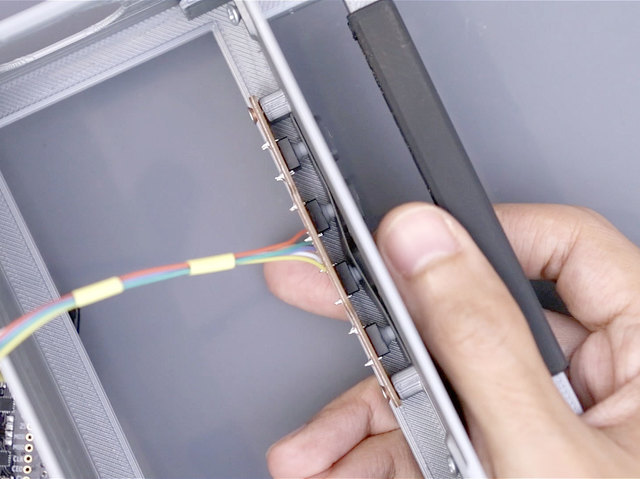
The acrylic window in the back cover lets you see whats inside. Etched into the panel are traces from Lady Ada's Speaker Bonnet board design from Eagle. Adorned to the speakers are vinyl stickers of the Raspberry Pi and the OctoPrint octopus. The USB and miniHDMI ports are accessible via a recessed purple panel.

Prerequisite Guides

If your new to electronics and the Adafruit Speaker Bonnet for Raspberry Pi, I suggest you walk through the following guides to get the basics. The guides below will walk you through setting it up.

Parts & Components

You'll need just a couple a parts to build this project. We suggest picking up the Stereo Bonnet Pack for Raspberry Pi Zero W, which includes the Pi Zero W and speaker set.

Angled shot of an assembled Stereo Bonnet Pack for Raspberry Pi Zero W - Includes Pi Zero W.
Remember those cereal commercials that would always say, "part of a complete breakfast"? Well the Pi Zero's a lot like that bowl of cereal - while it's...
Out of Stock
1 x Raspberry Pi Zero W
with WiFI included!
1 x PowerBoost 1000C
Rechargeable 5V Lipo USB Boost @ 1A - 1000C
1 x 3.7v 2200mAh Battery
Lithium Ion Cylindrical Battery
1 x Stereo Speaker Bonnet
Adafruit I2S 3W Stereo Speaker Bonnet for Raspberry Pi - Mini Kit
1 x Pimoroni Pico HAT Hacker
Full access to all 40 pins
2 x Male Headers
Break-away 0.1" 2x20-pin Strip Dual Male Header
1 x Slide Switch
Breadboard-friendly SPDT Slide Switch

Tools & Supplies

Hardware, cutters, solder, wires, that sorta thing.

1 x M2.5 Screw Tap
M2.5–0.45 METRIC COARSE THREAD TAPER TAPS
2 x M2.5 Machine Screw w/ Washers
M2.5 x .45 x 12MM
2 x M2.5 Machine Screws
M2.5 x .45 x 8MM
1 x 26AWG Wire
Silicone Cover Stranded-Core Wire - 26AWG in Various Colors
1 x 30AWG Wire
Silicone Cover Stranded-Core Wire - 30AWG in Various Colors
1 x Solder Wire
Solder Spool - 1/4 lb SAC305 RoHS lead-free / 0.031" rosin-core - 0.25 lb / 100 g
1 x Heat Shrink Tubing
Multi-Colored Heat Shrink Pack - 3/32" + 1/8" + 3/16" Diameters
1 x Mounting Putty Tack
Loctite Fun-Tak Mounting Putty 2-Ounce

Cool Tools!

These things really do help make building the project smoothly. You don't need them all of them, but I recommend them.

1 x Ultimaker 3
3D Printer
1 x Wire Strippers
Hakko Professsional Quality 20-30 AWG Wire Strippers - CSP-30-1
1 x Wire Cutters
Flush diagonal cutters - CHP170
1 x Soldering Iron
Adjustable 30W 110V soldering iron - XY-258 110V
1 x Panavise
Panavise Jr. - PV-201
1 x Helping Third Hands
Helping Third Hand Magnifier W/Magnifying Glass Tool - MZ101

3D Printed Parts

All of the parts are 3D printed with FDM type 3D printers using various colored filaments. All of the parts are separated into pieces to make 3D printing easier. Assembly is pretty easy and straight forward. Use the links below to download the STLs files.

What If I Don't Have A 3D Printer?

Not to worry! You can use a 3D printing service such as 3DHubs or MakeXYZ to have a local 3D printer operator 3D print and ship you parts to you. This is a great way to get your parts 3D printed by local makers. You could also try checking out your local Library or search for a Maker Space.

Multi-Color Parts

Boomy's face plate was 3D printed in different colored filaments. This can actually be done with single extruder 3D printers – dual extrusion is not required! To achieve a multi-color effect, the face and buttons are designed to be 3D printed in different gcode files. Follow our previous guide to learn how to use this technique in 3D printing slicing software.

Ninjaflex Buttons

The button actuators can be 3D printed in ninjaflex filament. There's several different types of TPU / rubber filaments, such as FilaFlex, Cheetah, and Tough Ink. Any of them should be suffice. I used Tough Stuff Impact black from Micro3D. If your 3D printer isn't capable of using TPU, you can optionally use hard PLA filament and split the buttons into pieces so they're separated from each other.

Case Assembly

The parts in this assembly are secured together with a combination of hardware and snap fit. The handle grip, for example, simply clips onto the handle bar. The bar is secured to the box frame with machine screws.

Mounting Plate Assembly

The mounting plate is installed and secured to the box frame with longer M2.5 x 12mm machine screws and two M2.5 nuts.

Board Assembly

This animated GIF shows how the boards are secured to the mounting plate with hardware. A combination of M2.5 flat Phillips screws and hex nuts are necessary to mount the PCBs to the standoffs. 

Button Assembly

The soft buttons are actuated with a 3D printed Ninjaflex buttons. These 8mm switches are mounted to a PCB or 3D printed plate. The plate is secured to the side off the case with 2x M2.5 machine screws.

Speaker Assembly

The speakers feature tabs with mounting holes. These are press fitted into the tabs holders on the inside of the case.

3D Model & Components

All of the parts were designed in Autdoesk Fusion 360 and available to download and modify. The source contains 3d models of components such as the speakers, Raspberry Pi, and Adafruit Speaker Bonnet. You can use these models for reference in your future enclosure designs!

Screw Tap

The mounting plate has several standoffs for mounting the PCBs. You'll want to use an M2.5 size screw tap to create threads in the standoffs of the mounting plate. This makes fastening the screws much easier than creating threads with screws. 

3D Printed Case

The case is a fairly large part to 3D print – 140mm x 80mm x 50mm. To speed up the print time, I suggest setting the layer height to 0.3mm. This part does not require a fine resolution, so printing at a 0.3mm layer height is suffice. This part does not require any support material.

Clip Grip onto Handle

The handle grip is designed to snap and clip onto the center of the handle bar. Install the grip so the opening is facing the bottom of the bar. You'll need to use a bit of force to clip the grip onto the bar. 

Attach Handle to Case

You'll need two short #4 wood screws to secure the handle assembly onto the case. Insert the ends of the handle bar onto the little indentations on the side of the case. Then, hold the handle assemble onto the case and insert the screws at an angle. Fasten until fully tightened.

Case Assembly

You'll want to test fit the case assembly. It's important to use the right size screws or else things might now line up perfectly. I highly suggest using a screw tap to create threads in the mounting plate. You an optionally use glue in places where it works, like the handle assembly. 

Install Port Plate

A separate plate features various opening for the USB and HDMI ports.  This will need to be secured to the cover with glue or adhesives. The orientation matters here, so make sure to reference the photos.

Acrylic Window

If you have access to a laser cutter or CNC mill, you can cut out a window from a piece of 1/8in(3.17mm) thick acrylic sheet. I milled mine on a Bantam Tools desktop CNC. I was able to engrave Lady Ada's Speaker Bonnet eagle board file using the Bantam Tools CNC software.

You may find this easiest if ssh is enabled on the Pi, and then log in with a terminal app. This lets you copy-and-paste the commands that follow, as they’re very exact about spelling.

Support for the Airplay emulation software and GPIO controlled buttons are installed separately. 

Do not proceed until you have your Speaker Bonnet up and running!

Install Shairport Sync

Shairport Sync is a Airplay audio player that can run on the Raspberry Pi. You can follow the step by step guide on installing the libraries and software on ThePi.io website.

Install GPIO Buttons

The four buttons are hooked up to GPIO pins on the Raspberry Pi. These control volume, mute audio or safely shut down the Pi.

Grab Dependencies

We'll want to install a few things before we get our controls python script running. Use this command to get them.

$ sudo apt-get install git python-pip python-gpiozero festival

To install the requirements, run this command.

$ sudo pip install pyalsaaudio

Install Controller Script

Now we can make the script by creating a new file and pasting the code using this command.

cd ~pi

sudo nano control.py

Then, copy and paste the code below into the newly created file. You can change up how the controls are mapped the GPIO by updating the buttons values at the top of the script.

# sudo apt-get install python-pip python-gpiozero festival
# sudo pip install pyalsaaudio

from gpiozero import Button
from signal import pause
import alsaaudio
import os
import time

mixer = alsaaudio.Mixer('PCM')
volup_button = Button(17)
voldown_button = Button(23)
mute_button = Button(27)
power_button = Button(22)

VOLUME_INCREMENT = 1

muted = False
volume_left, volume_right = mixer.getvolume()
print("Volume: L: %d%%    R: %d%%" % (volume_left, volume_right))

def volume_up():
  global volume_left, volume_right

  print("volume up!")
  volume_left, volume_right = mixer.getvolume()
  volume_left = min(volume_left + VOLUME_INCREMENT, 100)
  volume_right = min(volume_right + VOLUME_INCREMENT, 100)
  print("L: %d%%    R: %d%%" % (volume_left, volume_right))
  mixer.setvolume(volume_left, 0)
  mixer.setvolume(volume_right, 1)

def volume_down():
  global volume_left, volume_right

  print("volume up!")
  volume_left, volume_right = mixer.getvolume()
  volume_left = max(volume_left - VOLUME_INCREMENT, 0)
  volume_right = max(volume_right - VOLUME_INCREMENT, 0)
  print("L: %d%%    R: %d%%" % (volume_left, volume_right))
  mixer.setvolume(volume_left, 0)
  mixer.setvolume(volume_right, 1)

def mute():
  global volume_left, volume_right, muted

  if muted:
    print("Un-muting")
    muted = False
    mixer.setvolume(volume_left, 0)
    mixer.setvolume(volume_right, 1)
  else:
    print("Muting")
    muted = True
    mixer.setvolume(0, 0)
    mixer.setvolume(0, 1)

mute_button.when_pressed = mute

print("ALSA volume control friend!")

while True:
  if volup_button.is_pressed:
    volume_up()
    time.sleep(0.05)
  if voldown_button.is_pressed:
    volume_down()
    time.sleep(0.05)
  if power_button.is_pressed:
    t = time.time()
    while power_button.is_pressed:
      if (time.time() -t > 3):
        print("shutting down")
        os.system('echo "I am Boomy The Boom Box and I am shutting down now" | festival --tts')
        os.system("shutdown -h now")

Autostart Config

We can modify a startup file so that the script will automatically run when the Pi reboots.

$ sudo nano /etc/rc.local

Scroll down the script and enter the following text right above the line with exit 0.

sudo python /home/pi/control.py &

Then press cntrl+x to exit and enter to save changes to the file and exit. You'll want to reboot the Raspberry Pi. 

Circuit Diagram

This provides a visual reference for wiring of the components. They aren't true to scale, just meant to be used as reference. The Raspberry Pi isn't shown here because the Speaker Bonnet installs on top of it. The PowerBoost provides voltage to the Pi through the Speaker Bonnet. The buttons are wired to the GPIO pins on the Speaker Bonnet – These are broken out on the side of the header and nicely labeled.

Wired Connections

The Speaker Bonnet connects to the Raspberry Pi's GPIO header. The 2200mAh battery plugs directly into the PowerBoost. The 2x speakers directly connect to the Speaker Bonnet.

  • G from PowerBoost to GND on Speaker Bonnet
  • 5V from PowerBoost to 5V on PowerBoost
  • Switch to EN on PowerBoost
  • Switch to GND on PowerBoost
  • Button 1 to 17 on Speaker Bonnet
  • Button 2 to 27 on Speaker Bonnet
  • Button 3 to 22 on Speaker Bonnet
  • Button 4 to 23 on Speaker Bonnet

Pi Headers

To install the Adafruit Speaker Bonnet to the Raspberry Pi, we'll need to configure header pins so that the Bonnet can seat on top of the Raspberry Pi Zero W. In order to fit inside the 3D printed enclosure comfortably, we need to slightly offset the bonnet. We can do this with the Pico HAT Hacker from Pimoronoi. 

Header Configuration

There's a few different ways to setup the headers. Do you want to be able to swap out the Pi? Then you may want to install a Female Header in between the boards.

Pi Male Headers

We'll need to install a set of 2x20 male header pins to the Raspberry Pi Zero W. These will need to be soldered in, but if you'd like to skip soldering, you can give the Hammer Header pins a try. 

Pi GPIO Header Jig

I used a 3D printed jig to keep the headers held straight onto the Pi so the pins are nice and true. Then I secured the assembly to the jaws of a panavise Jr and soldered the pins. You can download the STL here.

Install PICO HAT

With the male headers now installed onto the Pi, we can seat the PICO hat on top. The second set of GPIO should be free and accessible above the set of male headers on the Pi, like in the photo. To keep these two boards straight, I used a few pieces of mounting tack.

Solder PICO Hat

Now we can secure the PICO hat to the male header pins on to the Pi by soldering them in. I used a panavise Jr. to keep the assembly sturdy while soldering everything together.

Trim PICO Pins

The male headers on the Pi are a bit lengthy, so it's a good idea to trim them short with a pair of flush diagonal cutters.

Install Headers to Bonnet

We'll need another set of male 2x20-pin header pins. These will need to be seated to the bottom of the Speaker Bonnet.

Connect Headers

Using the same 3D printed jig, I soldered all of the header pins to the Speaker Bonnet. You do have the option to use Hammer Headers if you'd like to skip all that soldering.

Install Speaker Bonnet to Pi

Seat the male headers from the Speaker Bonnet to the available GPIO pins on to the PICO hat. Press the boards together so their headers sit flush with each other.

Connect Speaker Bonnet to Pi

Now we can solder the male header pins from the Speaker Bonnet to the pins on the PICO hat. Again, using a Panavise Jr to keep everything sturdy while soldering. 

Trim Header Pins

The male header pins from the Speaker Bonnet are a bit lengthy so we can use flush snips to trim them short. After that, we have our Pi assembly ready to connect to the rest of the circuit!

Switch for PowerBoost

We'll wired up a slide switch to the PowerBoost 1000C. Make two pieces of wire about 14cm in length – I used 26AWG. Prep the slide switch by cutting off one of the legs, either the far left or right, but not the middle! Then, trim the remaining two legs so they're about half the length.

Tin Wires

Using wire strippers, remove a bit of insulation from the tips of both wires. Then, tin the bare strands of wire by adding a tiny bit of solder to them. Add a piece of heat shrink tubing to keep the two wires together.

Solder Wires to Switch

Attach the two wires to the legs of the switch by soldering them together.

Connect Switch to PowerBoost

Solder the wires from the switch to the EN and GND labeled pins on the PowerBoost.

Connect PowerBoost to Pi

We'll need to power the Pi and Speaker Bonnet with the PowerBoost. Make two more pieces of wire, about 14cm in length. Using wire strippers, remove a bit of insulation from the tips and tin them with a bit of solder. Pieces of heat shrink tubing can keep these two together. 

Connect Wires to PowerBoost

Solder the wires to the 5V and GND labeled pins on the Adafruit PowerBoost.

Connect PowerBoost to Speaker Bonnet

In order to power the Pi with the PowerBoost, we'll need to connect the 5V and GND wires to the pins on the Adafruit Speaker Bonnet. 5V and GND pins are conveniently broken out on top of the Speaker Bonnet. Solder in the two wires from the PowerBoost into any available 5V and GND pins.

PowerBoosted Pi

And now we have the PowerBoost wired up to the Adafruit Speaker Bonnet. This will also power the Raspberry Pi Zero W. 

Button PCB Eagle

If you have access to a CNC mill and you'd like to make your own custom PCB, you can download my button PCB eagle cad file. I was able to machine this PCB onto a FR-1 single-sized copper board using a 1/32" flat endmill on the Bantam Tools desktop CNC.

Button Wires

Next up we'll secure 4x buttons to a mounting plate and wire them up. I CNC milled a PCB to make this easier, but you can use a 3D Printed "PCB" to do similar. You'll need five new pieces of wire to connect the buttons to the Pi. These wires can be 30AWG size and about 16cm in length. 

Tin Wires

You'll want to use wire strippers to remove a bit of insulation and tin the tips with a bit of solder. I used different colored wires to help tell apart the various button connections. Some pieces of heat shrink tubing a great for keeping them wires bundled together.

Install Buttons

Seat the buttons onto the PCB (the 3D printed mounting plate) by inserting the legs of the buttons into the little holes and press them down to fully seat the buttons flush with the PCB. Try to avoid bending any of the legs on the buttons.

Connect Wires to Buttons

Now we can connect the wires to the buttons. Each button has four legs – two for signal and two for ground. You'll have to tie all of the grounds together so that all of the buttons connect to ground. Then, connect the rest of the wires to the signal leads, which are on the other side of the ground connections. This might get a little hairy, hence why I CNC milled myself a PCB =]

Connect Button Assembly

And with our buttons wired up, we can now connect them to the Pi. We'll solder into the available GPIO pins on top of the Speaker Bonnet. 

Solder Wires

Connect the wires from the buttons to the following GPIO labeled pins on top of the Adafruit Speaker Bonnet. Note, these are not the actual pin numbers, these are the GPIO numbers, which are totally different. They're conveniently labeled on the Speaker Bonnet.

  • #17
  • #27
  • #22
  • #23
  • GND

Final Circuit

And with that, we now have our final circuit wired up and ready to install into the 3D printed case! Now is a great time to do any last wire adjustments. Double check your wiring!

Secure PCBs to Mounting Plate

The Raspberry Pi assembly and PowerBoost are secured to the mounting plate using various M2.5 machine screws. Follow the photo for the correct orientation of the boards.

Mounting Pi

The Pi assembly requires 2x short M2.5 x 5mm screws in the front and longer M2.5 x 8mm screws on the back – Because of the PICO hat. 2x M2.5 washers can secure the longer screws.

Mount PowerBoost

Place the PowerBoost board over the four standoffs and hold it in place. Use 4x short M2.5 x 5mm screws to secure the PowerBoost to the four standoffs. Insert the screws and hold the board in place while fastening until fully tightened.

Install Button Actuators

Insert the button actuators into the button hole cutouts. The base will keep them from falling through. Orientate the case so the button actuators stay in place.

Mount Button PCB

Place the button PCB over the two standoffs that are next to the button actuators. Line up the mounting holes with the standoffs. While holding the button PCB in place, insert and fasten 2x M2.5 x 5mm short machine screws. Fasten until fully tightened.

Test Buttons

It's a good idea to test out the button actuators by pressing them to see how they feel. They should be press in freely, independent from each other when pressed. If you used hard PLA plastic to print them, you may need to cut them up so they're separated into individual pieces.

Speakers Graphics

I added some maker stickers to the outside case of the speakers. Since we'll be able to see inside the case, I thought it'd be nice if there was some cool graphics. I used Sparky the blue monster and an OSH Park sticker, but also a Raspberry Pi and OctoPrint octopus looks pretty cool. 

Install Speakers

The left and right sides of the case features holes for the speakers. On the side of the case are two tabs. These tabs actually hold the speakers in place without having to use any glue or screws. Orient the speaker so the openings line up with the speaker cone. Then, insert the speaker so it slides in between the tabs. Firmly press them in so the tabs click into place. 

Speaker Installation

Repeat the speaker installation process for the second speaker. Try to keep the wires from being kinked when pressing them into the tabs. You may need to press firmly to get the right speaker in because there's a feature on the side of the case (it's for holding the switch). 

Speaker Holes

The speaker cones should be properly oriented and lined up with the holes in the case. 

Install Mount to Case

Carefully insert the mounting plate into the case with the ports facing the outside. Line up the two tabs on the side of the plate with the standoffs on the case. The mounting holes should be lined up as well.

Insert Screws

While holding the mounting plate in place, insert longer M2.5 x 10mm sized screws into the holes on the outside of the case. Drive the screws until they protrude through the  tabs on the mounting plate.

Secure Mounting Plate

To properly secure the mounting plate to the case, we'll need to install 2x M2.5 washers. This can be a little tricky to get your fingers into the case at this point, so I suggest using tweezers to place the washer on to the screw threads. Fasten the screws until fully tightened. 

Connect Speakers

At this point, we can go ahead and connect the speakers to the Speaker Bonnet. This stereo speaker set features a male JST connector, so it's easily to plug it directly into the Speaker Bonnet.

Trim Speaker Wires

You may find the speaker wires are pretty lengthy – which is nice for some projects but a bit excessive once you stuff it into the case. To make it nice and neat, I shortened the length of the speaker wires. But this is entirely optional, totally up to you! If you do decide to trim the wires short, you'll want to measure them to determine how much wire is needed to reach and still connect to the Speaker Bonnet.

Splice Wires

Using wire cutters, clip the speaker wires. It's a good idea to strip and tin the wires. A bit of solder can splice these wires together – Just make sure to match up the grounds and voltage wires. Be sure to add a piece of heat shrink tubing before soldering wires together to protect and insulate the wires and avoid any shorts.

Short Speaker Wires

Here's how mine turned out. I left a little extra slack because that will make it easier to work with if I ever need to take the speakers out of the case. There is plenty of room inside the case, so some extra wire is OK.

The Battery

For this project I choose a 2200mAh battery but we can totally fit a bigger battery, like this beefy 6600mAh one. So if you want a longer lasting battery and you don't mind paying a little extra, go for it!

Connect Battery

Which ever battery capacity you choose, all of the ones carried by Adafruit can easily plug into the PowerBoost. 

Mount Battery

Since we can choose different sized batteries, I didn't design a specific mounting fixture for the battery. So I choose to secure mine to the top of the Speaker Bonnet with some mounting tack. I recommend doing this so the battery doesn't rattle around inside the case.

Stickers

Since we'll be able to see inside the case, I though it'd be cool to add some additional graphics. On the back of the faceplate, I stuck one of these lovely Adafruit stickers – These come with the Adafruit Circuit Playground Express. It features a reflective silver coating with the Adafruit text stylized as circuit traces. I think these are super cool and they're just the right size!

FacePlate

For perfect placement, I carefully placed the sticker centered. I used a squeegee to flatten the sticker to avoid any air bubbles. Well placed sticker!

Install FacePlate 

I used some double-sided tape to secure the faceplate to the case. You can optionally use glue or other type of adhesive, I found mounting tack even works. Maybe velcro, magnets? Get Creative!

Install Switch

The slide switch can be mounted to the back cover by pressing it into the little holder. It should stay in place with friction, but I suggest adding some mounting tack or adhesive to ensure the switch doesn't come out.

Snap Fitted Cover

Orient the cover so the port holes line up with the connectors and press the cover into the case. Firmly press the edges together so the nubs on the case snap into the lip on the cover. These two will click together. You can open up the enclosure by pulling out the cover if you need to.

Final Assembly

And now we can try it out! When the battery gets low, a red status LED will light up on the PowerBoost. Plug in a microUSB cable to the PowerBoost to recharge the battery – A yellow LED indicates charging. Green LED means the battery is fully charged and ready for use. 

Raspberry Pi Access

If you ever need to access the Raspberry Pi, you can still connect a USB keyboard, mouse and HDMI monitor. For example, if you travel and need to change the WiFi credentials. For updating the Pi software, you can SSH into it remotely from your desktop.

Share Your Make!

We'd love to see your photos and videos of your make! Post your stuff on your social network of choice and tag #AdafruitBoomyPi. Get a free Adafruit Sticker by showing it off on our Live Show & Tell Google Hangout.

This guide was first published on Nov 08, 2017. It was last updated on Mar 08, 2024.