Install the GT2 Timing Pulley
Insert the timing pulley into shaft of the stepper motor with the tightening bore end first. Reference the photo for the position.


Add Hardware to Camera Mount
The side with the counterbores will tightly fit #6-32 hex nuts. The easiest way to get'em in, is to press hex nuts into counterbores by laying the mount upside down top the nuts and using your hand/body weight to push down, ideally on a counter top table.
Once they're in, go ahead and grab the timing belt.


Install belt to camera mount
Now it's time to seat the belt onto the zigzag slot on the camera mount. The tension is pretty tight, so you'll need to widge the belt in, little by little starting on one side. The other slot is the "idler", the tolerance is loose so the belt can pass through. You'll need to keep the belt in place while we work with it.


Install Tripod Screw and Ball Head
Flip the camera mount over and you'll see the center hole has a counterbore. We need to insert a tripod screw here so the thread is protruding through the other side.
A standard tripod screw is typically 1/4"-20 size but the screw head may vary. The diameter of the opening here is 13.40 mm.
If your tripod screw doesn't fit, you may need to use a filing tool or adjust the model in CAD to widen the bore.
Once it can fit, insert and fasten it to the screw thread on the bottom of the tripod ball head. Tightly fasten them together.
The timing belt needs to be install before tripod mount because this keeps the belt from being unseated.


Install Camera Mount to Railing Platform
Insert and fasten four #6-32 3/4" screws into mounting holes on the platform. Grab the camera mount and lay that ontop of the railing platform. The screw threads should go through the bores. Use a screwdriver to fasten the screws into nuts.


Install railing platform onto support rail
OK, so this part requires you to be super careful. The railing platform comes with a plastic insert. DO NOT REMOVE IT!!! This plastic holder actually holds tiny ball bearings in place. The trick here is to insert the rail into the platform by pushing it through the rail, incrementally pushing the plastic holder out. To do this, I secured the platform to a panavise and slowly pushes the rail through the slider, pushing out the plastic bit. Make sure you have it in the proper orientation and do it slowly!


Add some Lube (Optional)
To make the railing platfrom slide across the support rail buttery smooth, I recommend adding some lubrication to the ball bearings.
Be super care if you decide to do this. When I did this the second time (the build for this tutorial) three little beads came out because the support rail came off too quick.
I was able to pop them back in though, but that was super lucky cause I found them on the desk.
Anyway, slowly and carefully pull the rail out of the platfrom, revealing only a small portion of the bearings. There's actually two rows of bearings on each side - it's difficult to see and I couldn't get any good photos of it but you'll see them. You only need to add one drop of Reel Better (synthetic oil for skate bearings) to each row. Once one side is lubed, carefully slide the platfrom the other way and lube the other side. Again, being super carefuls.


Install feet onto support rail
The feet should freely slide onto the support rail. Line up the mounting holes and insert a #6-32 3/8" screw through. Insert a hex screw to the bottom of the foot and fasten tightly. The hex nut should be seated in the counterbore. Go ahead and repeat this for the other side.


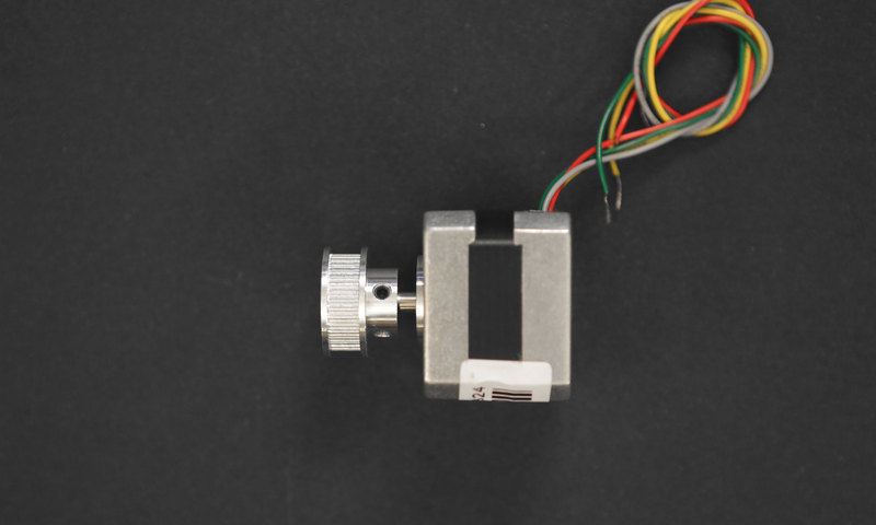
Install stepper motor to mount
Insert the stepper motor into the motor mount with the timing pulley going through the hole in the center. The stepper should be oriented with the wires facing the clips on the mount.
Insert four #4-40 3/8 screws into the mounting holes and fasten until they're flush.
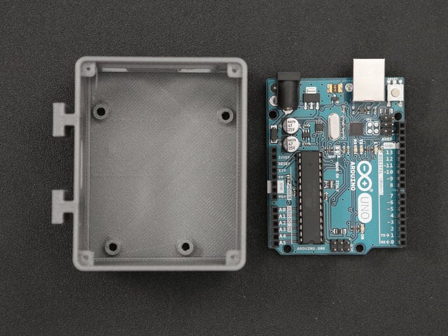


Install Arduino Uno into Enclosure
Next up we need to mount the Uno to the enclosure box. First, insert the PCB at angle with ports going in port into cutouts. This requires a bit of finesse. The stand-offs on the corners may get in the way, so you'll need to wiggle the PCB until it pops into place.
Once you get it in there, hold the PCB down in place with the mounting holes line up and insert four #6-32 3/8" screws. Fasten the screws tightly.
Rather than using nuts, these #6-32 screws "bite" into the PCB holes instead. This is normal.


Install Stepper Wires
OK, grab the stepper motor mount and position it closely to the enclosure box. Thread wires from stepper motor into cut out on enclosure. Pull them all the way through.
Now we can install the enclosure to the motor mount. Insert "T" shapes from enclosure to clips on stepper mount, being aware of the stepper wires - avoid clipping these while joining the parts!

Secure Motor mount to enclosure
Depeneding on how loose or tight the tolerances are, you may need to apply some adhesives to permanently attach the parts together. I recommend applying directly to the bottom of the clips and sliding them in.


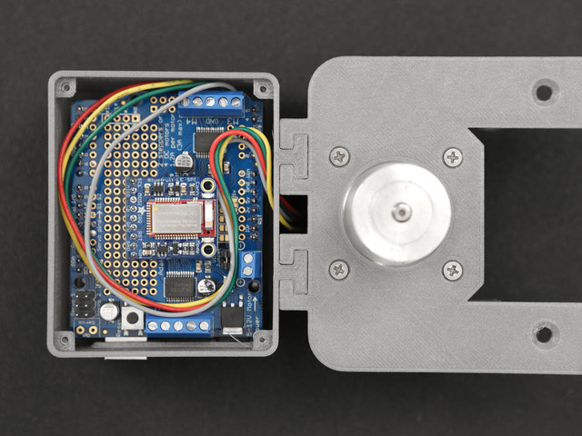
Install Stepper Wires to Motor Shield
The Motor Shield has terminals on the motor inputs so it's easy to insert them and tighten the screws to secure them in place.
Insert the wires from stepper motor to motor input M3 and M4. Follow the photo to reference order of wires using color as an indicator.
Next, insert the motor shield into enclosure with pins lined up with Arduino Uno.
Firmly press PCB down to install shield onto uno.


Close enclosure
Fit stepper wires into enclosure so it's nicely packed inside.
Next, let's insert and fasten four #2-56 3/8" screws into enclosure cover. Then, lay the cover ontop of the enclosure and fasten the screws tightly, until they're flush.
Now our motor and electronics portion is complete!


Install bearing and belt to pulley mount
OK, so before we can mount the bearing to the part, we need to insert the timing belt. Place the belt over the shaft and position it so the belt is up against the wall of the pulley guard. There's to lips that should keep the belt in line with the bearing. Once the belt is positioned, place the bearing over the shaft so it fits in. Firmly press it down until it snaps into place.
With the bearing and belt in place, you should be able to free pull on the belt to rotate the bearing. The tension should be not too tight or loose.
If it's too night, you may need to clean the inner wall of the bearing guard. There could be little bits of plastic left over from retraction.


Install Pulley Mount to foot
Insert two hex nuts on the bottom of the foot. Lay the mount over the foot and line up the mounting holes. Insert two #6-32 3/4" screws and fasten them tightly.


Install belt to timing pulley on stepper motor
Now we need to install the belt onto toothed timing pulley that's on the stepper motor. Once it's in place, play the mount over the foot and line up the mounting holes. Just like before, insert two #6-32 3/4" screws and fasten tightly.


Load Power Pack
Install 8 x AA batteries into battery holder. I recommend using rechargable ones. The battery holder features a standard barrel jack and plugs into the Arduino Uno.
It's a good idea to attach the battery pack to the enclosure. I didn't design a mounting bracket or anything special to do this because you may want a different battery pack or power source. I simply used double stick foam-tape but you could use veltro straps, zip ties or even adhesives to attach the battery box to the enclosure. You can acct it to either the bottom or top of the enclosure.
The 8 x AA battery holder also features a power switch!

Connect and Control
Congratulations, the build is complete!! All that's left is to do is test the connection and get some epic timelapses!
Download and launch the Adfruit bluefruit LE connect mobile on your device. Power on the Arduino. The Bluefruit LE module should appear in the list of devices. Tap on the connect button and then the control pad.
Now you can press the button to move the slider! Check the next page for usage details.


