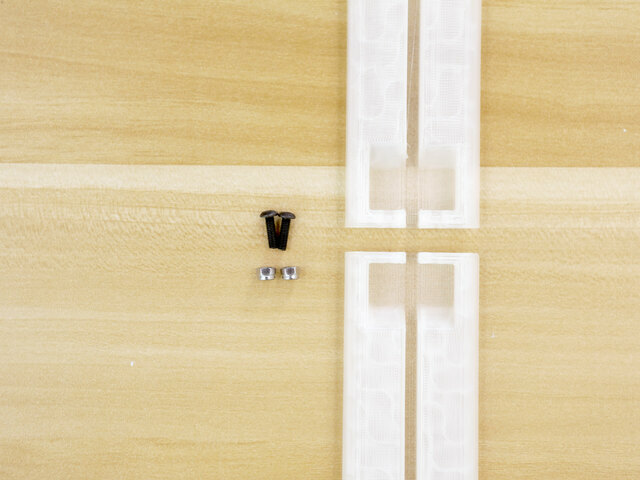


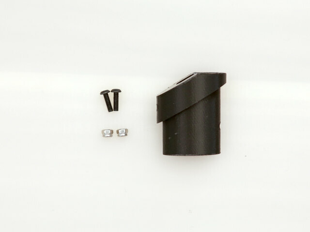
Hardware for Blade Parts
Use the following hardware to secure the two blade parts together.
- 2x M3 x 10mm pan head screws
- 2x M3 lock nuts with nylon inserts


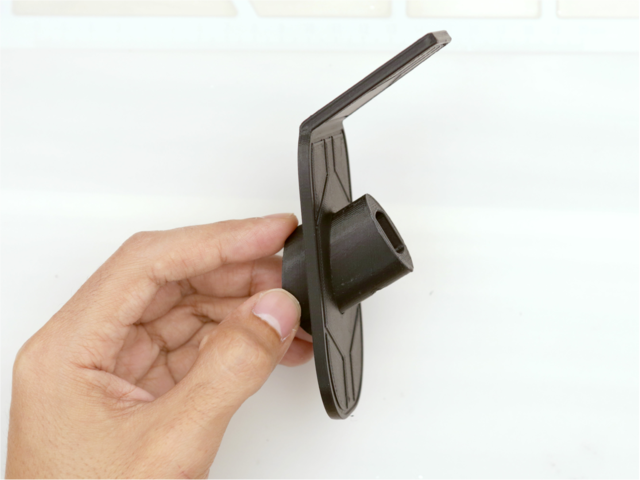
Install Nuts to Blade
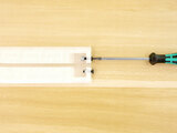
The M3 nuts are installed into cavities inside the lower blade part. The nuts have a very tight fit, so they must be installed by forcing them into place.
Insert an M3 x 10mm screw into the screw hole. Fasten the screw while holding the hex nut in place (use needle nose pliers). Fastening the screw will force the hex nut into the cavity.
Repeat process for the second screw hole. Unfasten the screw from the hex nut when it has been installed.


Secure Blade Parts
Insert the two M3 x 10mm screws into the screw holes in the second blade part. Join the two blade pieces together. Fasten the screws into the hex nuts until fully tightened.


Install Nut in Tang
An M3 lock nut is installed in to the screw hole near the tang of the blade. The installation process is similar to joining the two blade parts together. Use flat needle nose pliers to hold the nut in place while fastening an M3 screw. Fasten the screw until the hex nut is fully pressed into the cavity. Remove the screw when complete.


Install Strip to Blade
Alright, it's time to install the double-sided back-to-back mini skinny strip into the blade.
Carefully fit the NeoPixel strips into the slot in the center of the blade. Press the cabling into the tang.
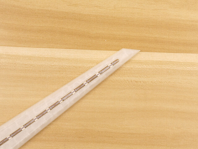


Installed NeoPixel Strip
Position the strips so it's reaching the very tip of the blade.
The NeoPixel strips are bent slightly just before reaching the tang.
The silicone cables are routed through the hole in the bottom of the tang.
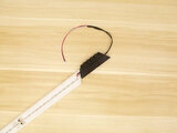
Test Blade with NeoPixel Strip
With the NeoPixel strips now fitted inside the blade, they can be tested with the PropMaker FeatherWing. Plug in the battery to the Feather to power on the circuit.


Installing Emitter
Insert the 3-pin JST cable from the strip through the top of the emitter part. Pull the cable all the way through the emitter and out the other end.
Reference the photo for installing the cable in the emitter in the correct orientation.

Install Blade to Emitter
Begin to fit the tang of the blade into the tip of the emitter. Orient the blade so the shape fits into the opening in the emitter.
Installed Blade
The blade should slide into the emitter with ease. Ensure the wiring is not being kinked when installing the blade into the emitter.


Secure Emitter to Blade
Use an M3x16mm long screw to secure the emitter to the blade. The screw should be long enough to reach the lock nut that was installed into the tang of the blade.
Tightly fasten the M3 screw to secure the emitter to the blade.


Installing Covers to Blade
The 4 cover pieces are attached to both sides of the blade. A piece of dark tape (vinyl with adhesive backing or electrical tape) is used join the covers together. This also prevents any light leaking from the seam.


Join with vinyl or Tape
Join the set of covers together. Note the chamfer near the edge where the two parts meet. This helps join the two parts together.
Carefully stick the piece of vinyl or electrical tape to the mating cover pieces. Use a hobby knife to trim away any access.


Attaching Covers to Blade
Double-sided nitto tape is used to attach the covers to the blade. Optionally use glues or other adhesives.
Using double-sided tape is nice because it allows the covers to be removed in case the LEDs ever need to be serviced.


Installed Blade Covers
Carefully place the cover onto the blade making sure the parts are lined up nicely. Start to lay the cover down near the tang and work towards the tip.
Apply a good amount of pressure to the covers to make the tape adhere to the surfaces.
Hardware for Coupler
The coupler is used to secure the blade emitter to the hilt. Use the following hardware to install the coupler.
- 2x M3 x 10mm pan head screws
- 2x M3 lock nuts with nylon inserts


Install Lock Nuts into Coupler
The two lock nuts are installed into cavities inside the coupler. Insert an M3 screw into one of the two holes. Use twisters to help fasten the hex nuts onto the thread of the screw. Fasten the screw until the lock nut is fully seated inside the cavity.


Continue Lock Nut Installation
Repeat this process for the second lock nut and screw hole.
An M3 x 16mm long screw is used in order to pass through the coupler.
The installation process is similar to the blade assembly.
Install Guard
The guard is installed onto the coupler. Orient the guard with the coupler and slip the guard over the coupler. Push the guard down so it sits flush with the coupler.

Installing Couple Cabling
Begin to insert the 3-pin JST cable from the NeoPixel strips through the coupler. Reference the photo for the correct orientation.


Install Coupler to Emitter
Insert the coupler into the bottom of the emitter. Ensure the wires are not being kinked when fitting the coupler. Push the coupler into the emitter until it's fully seated.

Secure Coupler to Emitter
Use an M3x10mm long screw to secure the emitter to the coupler.
Fully tighten the screw to secure the emitter to the coupler.


