Do you have trouble waking up? Do you keep forgetting to get in bed at a decent time? Are you impressively bad at remembering to take a certain pill twice a day? Do you keep forgetting about that one meeting for work until right before it starts? Do you have multiple stuffed sharks and no idea what to do with them? 

If any (or all) of these seem relatable, then this project is for you! While the scientific consensus is still out on whether stuffed sharks from Ikea help with the last one, I can certainly say that it has a decent chance of helping with all the others.

In this project, you'll take an Ikea Blåhaj (technically pronounced blow-high, although I've never pronounced it like that because it's not as fun as mispronouncing it on purpose) and add a Feather RP2040 with a small speaker to play an audio reminder, and an RTC (real-time clock) to keep the time.

Parts

In addition to the parts and tools on this list, you will need:

Angled shot of black rectangular microcontroller "Feather RP2040"
A new chip means a new Feather, and the Raspberry Pi RP2040 is no exception. When we saw this chip we thought "this chip is going to be awesome when we give it the Feather...
$11.95
In Stock
Prototyping feather wing PCB with loose headers
A Feather board without ambition is a Feather board without FeatherWings!This is the FeatherWing Proto - a prototyping add-on for all Feather boards. Using our...
$4.95
In Stock
Angled shot of a Stacking Headers for Feather - 12-pin and 16-pin female headers.
These two Female Stacking Headers alone are, well, lonely. But pair them with any of our Feather boards and...
$1.25
In Stock
Top view of a black speaker breakout board connected to a round microcontroller via alligator clips. A music note animation emits from the speaker.
Hey, have you heard the good news? With Adafruit STEMMA boards you can easily and safely plug sensors and devices together, like this Adafruit STEMMA Speaker - Plug and Play...
$5.95
In Stock
Angled shot of JST PH 3-pin Plug to Color Coded Alligator Clips Cable.
This cable will let you turn a JST PH 3-pin cable port into 3 individual wires with grippy mini alligator clips. We're carrying these to match up with any of our boards or...
$1.95
In Stock
Angled shot of PCF8523 Real Time Clock Breakout Board.
This is a great battery-backed real time clock (RTC) that allows your microcontroller project to keep track of time even if it is reprogrammed, or if the power is lost. Perfect for...
$4.95
In Stock
Angled shot of CR1220 12mm Diameter - 3V Lithium Coin Cell Battery - CR1220.
These are the highest quality & capacity batteries, the same as shipped with the iCufflinks, iNecklace, Datalogging and GPS Shields, GPS HAT, etc. One battery per order...
$0.95
In Stock
Angled shot of 4 Flora RGB Smart NeoPixel version 2.
What's a wearable project without LEDs? Our favorite part of the Flora platform is these tiny smart pixels. Designed specifically for wearables, these updated Flora NeoPixels have...
Out of Stock
Top view of Adafruit LC709203F LiPoly / LiIon Fuel Gauge and Battery Monitor powered by a Lipoly battery and an OLED display.
Low cost Lithium Polymer batteries have revolutionized electronics - they're thin, they're light, they can be regulated down to 3.3V and they're easy to charge. On your...
$6.95
In Stock
Stainless Medium Conductive Thread - 3 ply - 18 meter/60 ft
After months of searching, we finally have what we consider to be the ultimate conductive thread. It's thin, strong, smooth, and made completely of 316L stainless steel. Once you...
$9.95
In Stock

Get 2 of these

Angled of of JST SH 4-Pin Cable.
This 4-wire cable is 50mm / 1.9" long and fitted with JST SH female 4-pin connectors on both ends. Compared with the chunkier JST PH these are 1mm pitch instead of 2mm, but...
$0.95
In Stock
Angled shot of JST-PH 2-pin Jumper Cable - 100mm long
We use 2 pin JST PH connectors for all our battery packs, and if you want to put a board in series, like our LC709203F Stemma QT battery...
$0.95
In Stock
Lithium Ion Battery Pack with three round cells 3.7V 6600mAh with JST PH connector
Need a massive battery for your project? This lithium-ion pack is made of 3 balanced 2200mAh cells for a total of 6600mA capacity! The cells are connected in parallel and spot-welded...
Out of Stock
Hook-up Wire Spool Set in box with 6 colorful wires coming out
Perfect for bread-boarding, free wiring, etc. This box contains 6 spools of solid-core wire. The wire is easy to solder to and when bent it keeps its shape pretty well. We like to have...
$15.95
In Stock

Tools

Needle set - 3/9 sizes - 20 needles
Mighty needles, sew like the wind! This needle set is the only one you'll need for any sort of hand sewing, especially using our conductive thread and wearable electronics...
$1.95
In Stock
Two piece adjustable soldering iron with blobby temperature adjustable body and separate fancy holder
Known by engineers for making excellent quality tools & soldering irons! This is a genuine Hakko FX-888D with digital temperature control! We worked hard to get...
$129.95
In Stock
Solder Wire - 60/40 Rosin Core - 0.5mm/0.02" diameter.
If you want to make a kit you'll need some solder. This 0.1 lb (about 50 grams) spool is a good amount, not too much (like 1 lb spools) and not too little (like those little...
Out of Stock
Red and black multi-size wire stripplers, closed
These are the finest wire strippers we have used, and if you have to do a lot of wiring, you will agree! They have soft rounded grips - very comfortable to use, and precision ground...
$17.50
In Stock
Red and black diagonal flush cutters
These are the best diagonal cutters, large super-comfortable grip to use and have strong nippers for perfect trimming of wires and leads. I've used my pair every day for years.
$7.25
In Stock
Note: the Ikea Blåhaj may be difficult to find due to Ikea logistics and if they are going to continue stocking this item. Alternatives are to get one on the secondary market or use any stuffed animal, pillow, etc. and make the project your own.

CircuitPython is a derivative of MicroPython designed to simplify experimentation and education on low-cost microcontrollers. It makes it easier than ever to get prototyping by requiring no upfront desktop software downloads. Simply copy and edit files on the CIRCUITPY drive to iterate.

CircuitPython Quickstart

Follow this step-by-step to quickly get CircuitPython running on your board.

Click the link above to download the latest CircuitPython UF2 file.

Save it wherever is convenient for you.

To enter the bootloader, hold down the BOOT/BOOTSEL button (highlighted in red above), and while continuing to hold it (don't let go!), press and release the reset button (highlighted in blue above). Continue to hold the BOOT/BOOTSEL button until the RPI-RP2 drive appears!

If the drive does not appear, release all the buttons, and then repeat the process above.

You can also start with your board unplugged from USB, press and hold the BOOTSEL button (highlighted in red above), continue to hold it while plugging it into USB, and wait for the drive to appear before releasing the button.

A lot of people end up using charge-only USB cables and it is very frustrating! Make sure you have a USB cable you know is good for data sync.

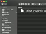
You will see a new disk drive appear called RPI-RP2.


Drag the adafruit_circuitpython_etc.uf2 file to RPI-RP2.

The RPI-RP2 drive will disappear and a new disk drive called CIRCUITPY will appear.

That's it, you're done! :)

Safe Mode

You want to edit your code.py or modify the files on your CIRCUITPY drive, but find that you can't. Perhaps your board has gotten into a state where CIRCUITPY is read-only. You may have turned off the CIRCUITPY drive altogether. Whatever the reason, safe mode can help.

Safe mode in CircuitPython does not run any user code on startup, and disables auto-reload. This means a few things. First, safe mode bypasses any code in boot.py (where you can set CIRCUITPY read-only or turn it off completely). Second, it does not run the code in code.py. And finally, it does not automatically soft-reload when data is written to the CIRCUITPY drive.

Therefore, whatever you may have done to put your board in a non-interactive state, safe mode gives you the opportunity to correct it without losing all of the data on the CIRCUITPY drive.

Entering Safe Mode

To enter safe mode when using CircuitPython, plug in your board or hit reset (highlighted in red above). Immediately after the board starts up or resets, it waits 1000ms. On some boards, the onboard status LED (highlighted in green above) will blink yellow during that time. If you press reset during that 1000ms, the board will start up in safe mode. It can be difficult to react to the yellow LED, so you may want to think of it simply as a slow double click of the reset button. (Remember, a fast double click of reset enters the bootloader.)

In Safe Mode

If you successfully enter safe mode on CircuitPython, the LED will intermittently blink yellow three times.

If you connect to the serial console, you'll find the following message.

Auto-reload is off.
Running in safe mode! Not running saved code.

CircuitPython is in safe mode because you pressed the reset button during boot. Press again to exit safe mode.

Press any key to enter the REPL. Use CTRL-D to reload.

You can now edit the contents of the CIRCUITPY drive. Remember, your code will not run until you press the reset button, or unplug and plug in your board, to get out of safe mode.

Flash Resetting UF2

If your board ever gets into a really weird state and CIRCUITPY doesn't show up as a disk drive after installing CircuitPython, try loading this 'nuke' UF2 to RPI-RP2. which will do a 'deep clean' on your Flash Memory. You will lose all the files on the board, but at least you'll be able to revive it! After loading this UF2, follow the steps above to re-install CircuitPython.

Putting batteries inside _anything_ is not always a good idea, make sure you know what you are doing and when in doubt, don't do it :)

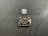
Insert the CR1220 battery into the PCF8523 with the positive side facing out. and attach a STEMMA cable to the RTC.

Connect the RTC to the LC709203 and attach a JST cable and another STEMMA cable to the LC709203.

Solder the stacking headers onto the Feather RP2040, then solder the normal headers onto the FeatherWing Proto. After this you can remove the FeatherWing proto board from the RP2040.

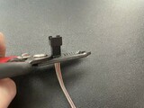
Take the JST PH 3-pin Plug and cut off the alligator clips on the end. Then strip and tin the wires. If you want to, you can add little bits of heat-shrink to the wire to make it look neater, but this isn't necessary.

Solder the leads that you just tinned onto the FeatherWing Proto. Solder the red wire to 3V, the black wire to GND, and the white wire to A0. Connect the JST wire to the STEMMA speaker.

Cut, strip, and tin 3 equal lengths of different colored wire. Here I'm using the red wire for power, the black wire for ground, and the yellow wire for data. Solder the red wire to the pad marked +, the black wire to the pad marked -, and the yellow wire to the pad marked with an arrow pointing towards the LED.

Solder the red wire to 3V, the black wire to GND, and the yellow wire to A1.

Before doing this you may want to put some heat-shrink around the 3 wires to make them a bit neater.

Now, cut, strip, and tin the wires from the NeoPixels. 

Solder the red wire to 3V, the middle wire to A2, and the outer wire to GND.

Cut the excess bits of wire from the underside of the proto-board.

Attach the battery to the empty JST jack on the LC709203 and plug the unconnected STEMMA cable and 2-pin JST from the LC709203 into the feather. Don't forget to put the proto FeatherWing back on it.

Download a zip of the project by clicking Download Project Bundle below.

After unzipping the file, you'll need to edit code.py. I'll explain the edits that need to be made below.

Before you do that though, you should copy the required libraries over:

  • adafruit_bus_device
  • adafruit_register
  • adafruit_lc709203f.mpy
  • adafruit_pcf8523.mpy
  • adafruit_pixelbuf.mpy
  • neopixel.mpy
  • simpleio.mpy
  • adafruit_led_animation
# SPDX-FileCopyrightText: 2022 Eva Herrada for Adafruit Industries
#
# SPDX-License-Identifier: MIT

import time

import board
from adafruit_lc709203f import LC709203F
import adafruit_pcf8523
from simpleio import tone
import neopixel
from adafruit_led_animation.animation.rainbow import Rainbow

i2c = board.I2C()  # uses board.SCL and board.SDA
# i2c = board.STEMMA_I2C()  # For using the built-in STEMMA QT connector on a microcontroller
rtc = adafruit_pcf8523.PCF8523(i2c)
battery = LC709203F(i2c)
indicator = neopixel.NeoPixel(board.A1, 1)

LEDs = neopixel.NeoPixel(board.A2, 20)
LEDs.fill((0, 0, 0))
rainbow = Rainbow(LEDs, speed=0.1, period=2)

days = ["Sunday", "Monday", "Tuesday", "Wednesday", "Thursday", "Friday", "Saturday"]
sleep = {
    0: (22, 50),
    1: (23, 8),
    2: (22, 50),
    3: (22, 50),
    4: (22, 50),
    5: None,
    6: None,
}
wake = {
    0: (11, 30),
    1: (9, 50),
    2: (9, 50),
    3: (9, 50),
    4: (9, 50),
    5: (9, 50),
    6: (11, 30),
}

BPM = 160

ringtone = [
    (330, 0.5),
    (294, 0.5),
    (185, 1),
    (208, 1),
    (277, 0.5),
    (247, 0.5),
    (147, 1),
    (165, 1),
    (247, 0.5),
    (220, 0.5),
    (139, 1),
    (165, 1),
    (220, 2),
]

SET_DATE = False  # Set this to True on first run and False for subsequent runs
if SET_DATE:
    # Make sure to set this to the current date and time before using
    YEAR = 2022
    MONTH = 3
    DAY = 21
    HOUR = 16
    MINUTE = 54
    SEC = 0
    WDAY = 1  # 0 Sunday, 1 Monday, etc.
    t = time.struct_time((YEAR, MONTH, DAY, HOUR, MINUTE, SEC, WDAY, -1, -1))

    print("Setting time to:", t)  # uncomment for debugging
    rtc.datetime = t
    print()

on_always = True  # Set to False for animation only to be on when alarm rings

indicate = True

start = time.monotonic()
wait = 1

while True:
    if on_always:
        rainbow.animate()
    if time.monotonic() - start > wait:
        start = time.monotonic()
        wait = 1
        t = rtc.datetime
        bat = min(max(int(battery.cell_percent), 0), 100)

        g = int((bat / 100) * 255)
        r = int((1 - (bat / 100)) * 255)
        if bat >= 15:
            indicator.fill([r, g, 0])

        if bat < 15:
            if indicate:
                indicator.fill([0, 0, 0])
                indicate = False
            else:
                indicator.fill([r, g, 0])
                indicate = True

        print(f"Date: {days[t.tm_wday]} {t.tm_mday}/{t.tm_mon}/{t.tm_year}")
        print(f"Time: {t.tm_hour}:{t.tm_min}:{t.tm_sec}")
        print(f"Batt: {bat}%\n")

        night = sleep[t.tm_wday]
        morning = wake[t.tm_wday]

        if night:
            if night[0] == t.tm_hour and night[1] == t.tm_min:
                for i in ringtone:
                    print(i[0])
                    tone(board.A0, i[0], i[1] * (60 / BPM))
                wait = 60
                if not on_always:
                    while time.monotonic() - start < 5:
                        rainbow.animate()
                    rainbow.fill([0, 0, 0])

        if morning:
            if morning[0] == t.tm_hour and morning[1] == t.tm_min:
                for i in ringtone:
                    print(i[0])
                    tone(board.A0, i[0], i[1] * (60 / BPM))
                wait = 60
                if not on_always:
                    while time.monotonic() - start < 5:
                        rainbow.animate()
                    rainbow.fill([0, 0, 0])

Setting the time

Set all the variables circled below to the current date and time.

Now that you have the time set in the code, copy cody.py to the CIRCUITPY drive which appears in your operating system File Explorer or Finder when the Feather is connected to your computer via a USB cable that is known to work for data transfer.

You'll now want to set the SET_DATE variable to False and copy it over to the CIRCUITPY drive again.

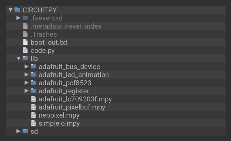
After you've copied all that over, your CIRCUITPY drive should look something like this:

CIRCUITPY

Code run-through

In this section I'll go through how the code works and what does what. I'd recommend reading this if you're planning on modifying the code but it's also very useful to read since part of this project involves setting the time and day for your alarms to go off.

First, the code makes the required imports.

import time

import board
from adafruit_lc709203f import LC709203F
import adafruit_pcf8523
from simpleio import tone
import neopixel
from adafruit_led_animation.animation.rainbow import Rainbow

Next, the code sets up the RTC, the LiPo charge indicator, the LED indicator, and the LED strip.

rtc = adafruit_pcf8523.PCF8523(board.I2C())
battery = LC709203F(board.I2C())
indicator = neopixel.NeoPixel(board.A1, 1)

LEDs = neopixel.NeoPixel(board.A2, 20)
LEDs.fill((0, 0, 0))
rainbow = Rainbow(LEDs, speed=0.1, period=2)

This next section is where the alarms are defined. The list titled days is used to make printing the day easier and shouldn't be changed.

The dictionary titled sleep is intended to be used as a reminder for the evening, and the dictionary titled wake is intended to be used as a reminder in the morning.

You set the alarm by setting it as a tuple in the value of the dict item. The key (0, 1, 2, etc.) denotes the day, with 0 being Sunday. The first item in the tuple is the hour, and the second item is the minute.

If you don't want an alarm to ring on that day, set the value of the dict item for that day to None.

days = ["Sunday", "Monday", "Tuesday", "Wednesday", "Thursday", "Friday", "Saturday"]
sleep = {
    0: (22, 50),
    1: (22, 50),
    2: (22, 50),
    3: (22, 50),
    4: (22, 50),
    5: None,
    6: None,
}
wake = {
    0: (11, 30),
    1: (9, 50),
    2: (9, 50),
    3: (9, 50),
    4: (9, 50),
    5: (9, 50),
    6: (11, 30),
}

Next, the BPM that the alarm sound will play in is set and the alarm itself is set as well. Each tuple in the list is a note. The first item in the tuple is the frequency, and the second item is the duration, in beats. If you'd like to change this, one website I found very handy was this tone generator. It has a list of notes and their frequencies if you click the box next to the music note.

BPM = 160

ringtone = [
    (330, 0.5),
    (294, 0.5),
    (185, 1),
    (208, 1),
    (277, 0.5),
    (247, 0.5),
    (147, 1),
    (165, 1),
    (247, 0.5),
    (220, 0.5),
    (139, 1),
    (165, 1),
    (220, 2),
]

This next section sets up the RTC. The first time you run the code, make sure to edit all the values (YEARMONTH, etc.) to the current date and time. After you first copy this over to the RP2040, you'll want to set SET_DATE to False and copy it over again. This ensures that the RTC won't get incorrectly set accidentally.

SET_DATE = True
if SET_DATE:
    # Make sure to set this to the current date and time before using
    YEAR = 2022
    MONTH = 3
    DAY = 10
    HOUR = 22
    MINUTE = 49
    SEC = 55
    WDAY = 0  # 0 Sunday, 1 Monday, etc.
    t = time.struct_time((YEAR, MONTH, DAY, HOUR, MINUTE, SEC, WDAY, -1, -1))

    print("Setting time to:", t)  # uncomment for debugging
    rtc.datetime = t
    print()

The code then sets a few variables and enters the main loop. First, the code updates the animation if that is set to be always on, then checks if enough time has passed to run the alarm logic again. If it has, the code gets the datetime from the RTC and the battery percentage from the LiPo meter. It then sets the color of the indicator LED to a gradient between red and green (full red being 0%, and full green being 100%). 

If the battery is below 15%, the indicator LED will flash on and off.

on_always = True  # Set to False for animation only to be on when alarm rings

indicate = True

start = time.monotonic()
wait = 1

while True:
    if on_always:
        rainbow.animate()
    if time.monotonic() - start > wait:
        start = time.monotonic()
        wait = 1
        t = rtc.datetime
        bat = min(max(int(battery.cell_percent), 0), 100)

        g = int((bat / 100) * 255)
        r = int((1 - (bat / 100)) * 255)
        if bat >= 15:
            indicator.fill([r, g, 0])

        if bat < 15:
            if indicate:
                indicator.fill([0, 0, 0])
                indicate = False
            else:
                indicator.fill([r, g, 0])
                indicate = True

For the second part of the main loop, the code prints a bunch of information that's useful for when you're connected to the RP2040 from a serial console and sets two variables that are the alarm times in the sleep and wake lists.

⠀   print(f"The date is {days[t.tm_wday]} {t.tm_mday}/{t.tm_mon}/{t.tm_year}")
	print(f"The time is {t.tm_hour}:{t.tm_min}:{t.tm_sec}")
	print(f"Battery: {bat}%")

	night = sleep[t.tm_wday]
	morning = wake[t.tm_wday]

The code then checks each of the two variables defined above to see if the user wants an alarm to be rung today. If so it then checks to see if it's time to ring that alarm. If it is, it plays the notes from the alarm sound and waits 60 seconds to ensure the alarm doesn't go off for the entire minute.

The code then waits for a second and runs the loop again.

⠀       if night:
            if night[0] == t.tm_hour and night[1] == t.tm_min:
                for i in ringtone:
                    print(i[0])
                    tone(board.A0, i[0], i[1] * (60 / BPM))
                wait = 60
                if not on_always:
                    while time.monotonic() - start < 5:
                        rainbow.animate()
                    rainbow.fill([0, 0, 0])

        if morning:
            if morning[0] == t.tm_hour and morning[1] == t.tm_min:
                for i in ringtone:
                    print(i[0])
                    tone(board.A0, i[0], i[1] * (60 / BPM))
                wait = 60
                if not on_always:
                    while time.monotonic() - start < 5:
                        rainbow.animate()
                    rainbow.fill([0, 0, 0])

Take your seam-rippers and cut a hole in the fin. large enough to fit your hand in comfortably. 

Take the cotton out of the fin so it'll be easier to sew the velcro in and insert the electronics.

Cut two lengths of velcro long enough to fill the hole you just created. Sew the velcro into the hole.

Start to insert the LEDs. At this point it wouldn't be a bad idea to connect the battery and set the code to the mode where the LED animation is always on so you can see what the LEDs look like in the Blahaj.

Insert the rest of the electronics and put the indicator LED somewhere it is easily visible through the fabric.

Seal the blahaj up with the velcro and it should be good to go!

This guide was first published on Mar 22, 2022. It was last updated on Apr 16, 2024.