There's so many Arduino's out there, it may get a little confusing. We wanted to clarify for people some of the changes in the latest version.

NB this is just our opinion and interpretation of some of the decisions made by Arduino. We aren't associated with Arduino, and don't speak for them! If you have to get an Official Response to your Arduino question please contact them directly. Thx!
NB2 Still in progress, we're collecting common questions to answer. If you have more questions, please post them in our forums.
NB2 Still in progress, we're collecting common questions to answer. If you have more questions, please post them in our forums.
Arduino Timeline
But first…some history! First there was the serial Arduino (what's the name of it?) with RS232 which was not used outside of the Arduino team & friends.The first popularly manufactured Arduino was called the NG (New Generation, like Star Trek, yknow?) The NG used the Atmega8 chip running at 16 MHz and an FT232 chip for the USB interface. The bootloader takes up 2KB of space and runs at 19200 baud.
The next version was the Diecimila. The Diecimila updated the chip from the Atmega8 to the Atmega168. The great thing here is double the space and memory (16K instead of 8K). It still ran at 16MHz. The Diecimila also added two extra header pins for 3.3V (from the FTDI chip) and the reset pin which can be handy when a shield is covering up the Reset button. The bootloader takes up 2KB of space and runs at 19200 baud. Auto-resetting was also added which makes life awesomer for everyone.
In 2009, the Duemilanove was released. This one also upgraded the chip again, to the Atmega328. Yet another doubling of space and memory! Another upgrade is now the power is automagically switched between USB and DC-jack which removed the previous jumper. This makes it easier and faster to move from programming to standalone and got rid of some confusion. The bootloader takes up 2KB of space and runs at 57600 baud.
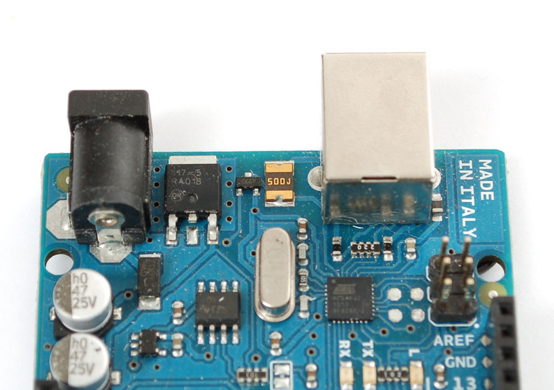
In 2010, we have the Uno! The Uno still uses the 328P chip and the power switcher. It has a smaller bootloader called OptiBoot (more space for users' projects) that runs at 115K. So even though the chip is the same, you get another 1.5K of extra flash space that was previously used by the bootloader. The FTDI chip has also been replaced with a atmega8u2 which allows for different kinds of USB interfaces. Finally, there's an extra 3.3V regulator (LP2985) for a better 3.3V supply. whew!
New USB Chip
So! All of the older Arduinos (NG, Diecimila and Duemilanove) have used an FTDI chip (the FT232RL) to convert the TTL serial from the Arduino chip (Atmel ATmega). This allows for printable debugging, connecting to software like PureData/Max, Processing, Python, etc. etc. It also allows updating the firmware via the serial bootloader.The good news about the FT232RL has royalty-free drivers and pretty much just works. The bad news is that it can -only- act as a USB/Serial port. It can't act like a keyboard, mouse, disk drive, MIDI device, etc.

The Uno has changed that by exchanging the FT232RL chip with an atmega8u2 chip. There are a few things that are possible with this new chip but before we discuss that lets make it clear that by default, this chip acts identically to the FTDI chip that it replaces. It's just a USB-serial port!
One improvement in updating the chip is that, previously, Mac users needed to install FTDI drivers. The 8u2 imitates a 'generic' CDC serial device. So now, Mac users do not have to install a driver. Windows users still need to install the .INF file but luckily there are no drivers. This means there will be fewer problems with new versions of windows. There is no way to have a serial USB device that doesn't require an INF file in windows, sadly :(
The big thing that is nice about the 8u2 is that advanced users can turn it into a different kind of USB device. For example it can act like a keyboard or mouse. Or a disk driver. Or a MIDI interface, etc. Right now there are no examples of how to do this, but we hope to post some shortly.
And, finally, going with the 8u2 reduced the price of the board which made up for some of the other extras.
Why not just go with a atmega32u4?
The Arduino team has indicated they thought about this but preferred that hackability of a DIP chip.
Right now there are a few Arduino's with a 32u4 chip such as the Leonardo, Micro and Esplora
Right now there are a few Arduino's with a 32u4 chip such as the Leonardo, Micro and Esplora
How can I change the USB firmware?
The 8u2 can be programmed by soldering a 6-pin ISP header (the R3 has the 6-pin header pre-soldered in) and using a standard AVR programmer. You can also use the bootloader (DFU) in the 8u2. On first generation Unos, you enable this by soldering the 10K resistor right underneath the board. (R2 and R3 versions of the Uno use the 16U2 and do not require the resistor!) Again, we don't have any examples or tutorials but hope to shortly.


The code for the 8u2 is based on LUFA, Dean Cameran's totally awesome USB-AVR library that has great examples and documentation. Its also completely open source.
Does the Uno use a resonator or a crystal for the processor clock?
The FT232RL had an internal oscillator whereas the 8u2 does not. That means there is a 16mhz crystal next to the 8u2 to allow it to keep up with precise USB timing.
On the other hand, the Atmega328p chip that is the core processor in the Arduino now has a 16mhz ceramic resonator. Ceramic resonators are slightly less precise than crystals but we have been assured that this one was specified and works quite well.
On the other hand, the Atmega328p chip that is the core processor in the Arduino now has a 16mhz ceramic resonator. Ceramic resonators are slightly less precise than crystals but we have been assured that this one was specified and works quite well.


So the Arduino is not as precise, timing-wise?
The short answer is: yes. The long answer is that most things that people are doing with Arduino do not rely on 20ppm precision timing where 100ppm would fail. For people who want long term precise timekeeping we suggest going with a TCXO (temperature compensation crystal oscillator) - but you would know if you needed that.
Why not have one 16Mhz crystal shared between both?
Good question, technically you can. However, in practice the board did not make it through FCC certification with one crystal (long traces with fast squarewaves = lots of noise).
OK well lets say I don't care about that...
You can absolutely connect the CLKO out the crystal from the '8u2 to the '328p but you're on your own as we don't think there will be any tutorials about that.
Whats with the FCC logo on the back?
Arduino is now FCC certified! That means that the board by itself passes FCC certification for electromagnetic emissions. It does not mean that your project is FCC certified. The moment you change the Arduino, it's no longer FCC certified (although we'd like some back-up documentation on this).

It is also, still, CE certified for Europeans.
A new Bootloader?
There's a new bootloader. It works just like the old one - being an STK500-protocol compatible but its a quarter of the size! Down from 2K, the new bootloader is a tiny 512b. This gives you more space for your project code! Yay! It's also faster - 115K instead of 57.6k so you'll be uploading code in 3 seconds.
The Bad News is that you must make sure to select Uno in the Boards menu!!! If you don't things will be confusing because the bootloader speed is wrong, and you won't get that extra 1.5K!
Overall, its a good direction, and the chips can be used in older Arduinos just fine (so you can upgrade your Diecimila or Duemilanove to the Uno by simply replacing the chip).
For more detailed information about the bootloader, such as source code, please visit the Optiboot project page.
Why not just use the '8u2 as a programmer?
While it is possible that the 8u2 could act as a full ISP programmer there are a few reasons why its good that it isn't.
- Giving beginners access to a full ISP programmer will result in bricked chips. There's no risk of messing up the Arduino chip beyond recognition if it's just being bootloaded
- Having the chip act only as a USB/serial passthrough simplifies the firmware so that the chip has only one function instead of having to have it do double duty as programmer -and- serial interface (think about it, its not easy)
- Backwards compatibility - the Arduino chips can still be programmed with FTDI breakout boards or cables, making it easy for people to breadboard or make clones.
How does the new '8u2 affect Arduino-derivatives?
Every USB device needs to have a unique product id and vendor id. Vendor IDs (VID) are sold to companies and Product IDs (PID) are chosen by that company. So for example FTDI owns VID #0403 and they give their chips ID's between #0000 and #FFFF (65,536 different PIDs) Older Ardiuno's used FTDI's VID/PID as that is part of the deal when you purchase their chips. Because the Uno does not use an FTDI chip anymore, the Arduino team had to purchase a USB Vendor ID (VID). Every Arduino product will now have their own PID starting with the Uno (#0001).
If you want to make your own Arduino-compatible board, you have a few choices:
If you want to make your own Arduino-compatible board, you have a few choices:
- Don't use an 8u2, go with an FTDI chip instead that comes with a VID
- If you're planning to make more than one board for your personal use, you will have to purchase a VID from USB IF for a one time $2000 fee
- If you're making a single board for your own experimentation, you can pick a VID/PID that doesn't interfere with any devices on your computer and substitute those in
- You can purchase licenses for single VID/PID pairs from companies that develop USB devices (we dont have any specific links at the moment)
I tried to find a place to buy some '8u2s and couldnt locate any!
Yep, there is a worldwide shortage of Atmel parts right now. Even the chip used in the Arduino core (Atmega328P) is really hard to get. This happens after recesssions. We hope that these and other Atmel chips will show up again in places like digikey soon. Till then, keep searching on findchips.com!
So does this mean there may be an Arduino shortage?
Probably not. The Arduino team buys chips in the 10's of thousands, directly from Atmel. They probably get priority over distributors because of this. We're assuming the team bought enough to last for a while.
Did the Arduino team move from the FTDI chip to the '8u2 to screw over derivative-makers?
While the appearance of a hard-to-get chip coupled with the VID/PID mishegas may seem to be a little annoying, we don't think that means that the Arduino team is being malicious or attempting to make life difficult for people who make derivatives. The move to an '8u2 makes the Arduino more powerful, and easy to use as there are fewer drivers to install. While there is a shortage now, there will eventually be plenty of chips on the market.
Some people in the Arduino forum have thought of forming a group that would purchase a VID for Arduinites to use in personal projects. This is a pretty good idea and its probably the best way to avoid VID/PID conflicts. Between 65,536 projects, that comes to under a nickel per PID.
And of course, because they didn't get rid of the bootloader system, you can always just use an FTDI chip.
Are Shields still going to work?
All previous shields should still work perfectly fine as the header spacing is the same, the core chip is the same and the location of parts is the same. In fact, some should work better because the 3V supply has been upgraded (see next point).
Will enclosures, plates, etc still work?
Yup! The Uno is physicially the same size and layout as previous Arduinos. The mounting holes are in the same location. There is an additional mounting hole as well, now.

One sad thing about older boards is that they had a 3.3v power supply but it was really just whatever the FTDI chip's internal 3.3v regulator could give. You -could- get 50mA out of it, maybe. But high power stuff like XBees, SD cards, some fast ADC or DACs could easily drag down the FTDI chip and reset the USB connection. The Uno solves this problem by adding a new 3.3V regulator the LP2985 which can easily provide 150mA.
The LP2985 is a very high quality regulator, and will work great for powering stuff and as a nice solid 1% analog reference.
The LP2985 is a very high quality regulator, and will work great for powering stuff and as a nice solid 1% analog reference.
Why is the Arduino chip running at 16MHz when it can run at 20MHz?
This is a common question. The reason is that the first Arduino used the Atmega8 which could not run faster than 16Mhz. As the chip has been upgraded they wanted to make the boards speed compatible. Arduino is also not really intended for fast-processing (its only 8-bit anyways) so the chips are running at 16MHz.
Is it still Open source hardware and software?
Yes! The Uno is still available under a Creative commons license. You can get the latest schematics and layouts over at the Arduino website.
UNO R2 and R3
During fall of 2011, the Arduino team revealed that there will be a new minor revision of the classic Arduino, the "UNO R3" (revision 3). A lot of people have asked us about the R3 so here is everything we know so far.- The UNO R3 is not available to resellers until December 1st or so. Really! Nobody has them until then!
- The UNO R3 is backwards compatible with the UNO - same driver, same uploading, same look
- The USB controller chip has moved from an atmega8u2 (8K flash) to an atmega16u2 (16K flash). This does not mean that you have more flash or RAM for your sketches this upgrade is for the USB interface chip only. In theory this will mean that it will be easier to have low level USB interfaces such as MIDI/Joystick/Keyboard available. However these are only theoretical at this time, there is no example code or firmware which will actually do this.
- There are three more breakout pins on the PCB, next to the AREF pin there is are two I2C pins (SDA/SCL) - this is a duplication of the Analog 4 and 5 pins. There is not an extra I2C interface or anything, its just that they made a copy of those pins there for future shields since the I2C pins are in a different place on Mega. There is also an IOREF pin which is next to the Reset pin - this is to let shields know what the running I/O pin voltage is on the board (for the UNO, its 5V). Again, this is a duplication of the power pin, it does not add voltage level shifting to the UNO.
- The RESET button has moved to be next to the USB connector, this makes it easier to press when a shield is on top.
- Processor size and speed - its the same ATMega328P running at 16MHz that we've had since the Duemilanove. Your code will not run faster or better on the R3
- Same number of pins - no extra pins are added EVEN THOUGH THERE ARE MORE BREAKOUTS (see above!)
- Board size and shape - same size as before
- Shield compatibility - Every shield that works and plugs into the UNO R1/R2 should be able to work fine with the R3
- Driver - the driver is the same
- Upload speed - same upload speed and technique