At this point, you should have just about everything already set up.
Besides the audio, the Voice Bonnet has quite a few other useful features on it that can be controlled through Python. We'll go through those and how to control them in Python.

The button uses simple digitalio, so it's really simple to control. Here's a little script that will setup the GPIO, create an internal pull up, and then print out the value to the terminal.
import time
import board
from digitalio import DigitalInOut, Direction, Pull

button = DigitalInOut(board.D17)
button.direction = Direction.INPUT
button.pull = Pull.UP

while True:
  if not button.value:
    print("Button pressed")
  time.sleep(0.01)
Go ahead and save the above code onto your Pi as button_test.py and run it with the following command:
python button_test.py
Now try moving the joystick and press the button and you should see it print out what you're pressing.


The 3 DotStar LEDS can be controlled with the DotStar CircuitPython Library. Here's a little script that will setup the DotStar LEDs and then color cycle them.
import time
import board
import adafruit_dotstar

DOTSTAR_DATA = board.D5
DOTSTAR_CLOCK = board.D6

dots = adafruit_dotstar.DotStar(DOTSTAR_CLOCK, DOTSTAR_DATA, 3, brightness=0.2)

def wheel(pos):
    # Input a value 0 to 255 to get a color value.
    # The colours are a transition r - g - b - back to r.
    if pos < 0 or pos > 255:
        return (0, 0, 0)
    if pos < 85:
        return (255 - pos * 3, pos * 3, 0)
    if pos < 170:
        pos -= 85
        return (0, 255 - pos * 3, pos * 3)
    pos -= 170
    return (pos * 3, 0, 255 - pos * 3)

while True:
    for j in range(255):
        for i in range(3):
            rc_index = (i * 256 // 3) + j * 5
            dots[i] = wheel(rc_index & 255)
        dots.show()
        time.sleep(0.01)
Go ahead and save the above code onto your Pi as dotstar_test.py and run it with the following command:
python dotstar_test.py
The DotStar LEDs should start color-cycling in a rainbow.

Parts
For this script, we'll just need one part that isn't included with the Voice Bonnet:

Wiring
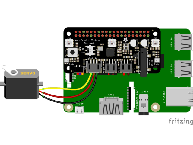
Code
import time
import board
import pwmio
from adafruit_motor import servo

SERVO_PIN = board.D12
pwm = pwmio.PWMOut(SERVO_PIN, frequency=50)
servo = servo.Servo(pwm, min_pulse=750, max_pulse=2250)

while True:
    for angle in range(0, 180, 5):  # 0 - 180 degrees, 5 degrees at a time.
        servo.angle = angle
        time.sleep(0.05)
    for angle in range(180, 0, -5): # 180 - 0 degrees, 5 degrees at a time.
        servo.angle = angle
        time.sleep(0.05)
Go ahead and save the above code onto your Pi as servo_test.py and run it with the following command:
python servo_test.py
The servo should start sweeping back and forth in 5 degree increments.

For the Stemma QT port, you can use any of our 50+ sensors, but we're going to use a script that demonstrates using the BMP280 because it's so simple.
Parts
For this script, we'll just need a BMP280 and a Stemma QT cable:


Wiring

- Connect one side of the Stemma QT cable to either port on the BMP280
- Connect the other side to the Stemma QT port on the Voice Bonnet
Code
# SPDX-FileCopyrightText: 2021 ladyada for Adafruit Industries
# SPDX-License-Identifier: MIT

"""Simpletest Example that shows how to get temperature,
   pressure, and altitude readings from a BMP280"""
import time
import board

# import digitalio # For use with SPI
import adafruit_bmp280

# Create sensor object, communicating over the board's default I2C bus
i2c = board.I2C()  # uses board.SCL and board.SDA
# i2c = board.STEMMA_I2C()  # For using the built-in STEMMA QT connector on a microcontroller
bmp280 = adafruit_bmp280.Adafruit_BMP280_I2C(i2c)

# OR Create sensor object, communicating over the board's default SPI bus
# spi = board.SPI()
# bmp_cs = digitalio.DigitalInOut(board.D10)
# bmp280 = adafruit_bmp280.Adafruit_BMP280_SPI(spi, bmp_cs)

# change this to match the location's pressure (hPa) at sea level
bmp280.sea_level_pressure = 1013.25

while True:
    print("\nTemperature: %0.1f C" % bmp280.temperature)
    print("Pressure: %0.1f hPa" % bmp280.pressure)
    print("Altitude = %0.2f meters" % bmp280.altitude)
    time.sleep(2)
Go ahead and save the above code onto your Pi as bmp280_simpletest.py and run it with the following command:
python bmp280_simpletest.py
The terminal should start printing out the detected measurements.


