LEDs
We love LEDs! There are three LEDs on board to help you with debugging and status updates:
Green PWR LED tells you that there is a good 3V power supply. If this isn't on, there's a serious problem with the power supply, perhaps the battery died
Yellow L13 (and SD card access) LED is connected to digital 13, this is handy for telling when the Arduino is bootloading and also will flicker whenever the SD card is accessed.
Red FIX LED is connected to the GPS's fix output. When this is turning on/off once a second it does not have a fix. When it blinks once every 15 seconds, the GPS has a fix.

Antennas
All Ultimate GPS shields have a built in patch antenna - this antenna provides -165 dBm sensitivity and is perfect for many projects. However, if you want to place your project in a box, it might not be possible to have the antenna pointing up, or it might be in a metal shield, or you may need more sensitivity. In these cases, you may want to use an external active antenna.
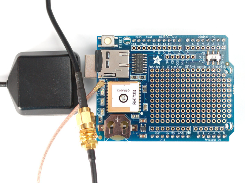
Most GPS antennas use SMA connectors, which are popular and easy to use. However, an SMA connector would be fairly big on the GPS breakout so we went with a uFL connector - which is lightweight, small and easy to manufacture. If you don't need an external antenna it wont add significant weight or space but its easy to attach a uFL->SMA adapter cable. Then connect the GPS antenna to the cable.
The Ultimate GPS shield will automagically detect an external active antenna is attached and 'switch over' - you do not need to send any commands
There is an output sentence that will tell you the status of the antenna. $PGTOP,11,x where x is the status number. If x is 3 that means it is using the external antenna. If x is 2 it's using the internal antenna and if x is 1 there was an antenna short or problem. On newer shields & modules, you'll need to tell the firmware you want to have this report output, you can do that by adding a gps.sendCommand(PGCMD_ANTENNA) around the same time you set the update rate/sentence output.

RTC Backup Battery
The Ultimate GPS module does not have a built in RTC battery, but a coin cell is provided, simply place the coin cell inside the holder, with the + facing up, thats it! The battery will last 7+ years
The real time clock will automatically set itself to the correct UTC time as soon as the GPS gets its first correct signal from a satellite. Without the battery, if the GPS loses power, it will forget the time and has to wait till it gets signal again to reset. But, if you have the battery in, it will keep time even after a power loss. We recommend it highly!

Breakout and Proto-area
Since the GPS module is so small, we had tons of space left over, we turned that into a proto area. Feel free to put any circuitry you'd like into the 0.1" spaced holes. None of the holes are connected.
There's also a few breakouts near the SoftSerial/Direct switch. For example, the PPS pin which provides pulse-per-second output when the GPS has a fix.
- 3V - this is the output from the onboard 3V regulator, it provides ~100mA if you need another 3V supply
- CD - this is the card-detect output from the microSD socket, it is shorted to ground when a card is not inserted. You'll want to have a pullup if you plan to use this pin to detect if a card is inserted
- CCS - this is another breakout for the Card Chip Select line. By default its connected to digital 10 but if you want to change it you can cut the trace from here to #10 and then solder in a new wire
- PPS - pulse-per-second output when the GPS has a fix
- TX and RX - extra 'copies' of the GPS RX/TX pins - the RX pin is 5V friendly.


