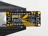
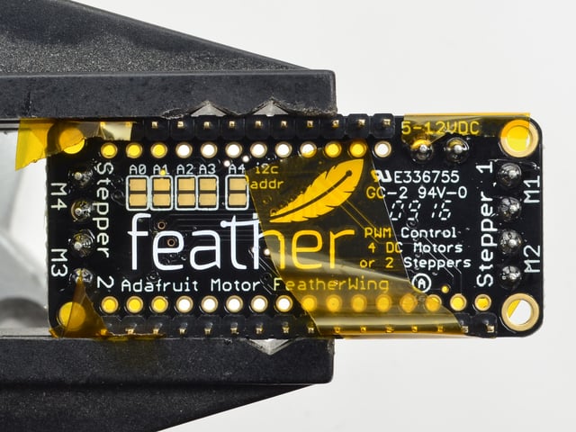
A Feather board without ambition is a Feather board without FeatherWings! This is the DC Motor + Stepper FeatherWing which will let you use 2 x bi-polar stepper motors or 4 x brushed DC motorx (or 1 stepper and 2 DC motors). Using our Feather Stacking Headers or Feather Female Headers you can connect a FeatherWing on top or bottom of your Feather board and let the board take flight!

The original Adafruit Motorshield Kit is one of our most beloved shields, which is why we decided to squish it all together on a FeatherWing to make something even smaller, lighter, and more portable! Instead of using a latch and the Arduino's PWM pins, we have a fully-dedicated PWM driver chip onboard. This chip handles all the motor and speed controls over I2C.

Since the FeatherWing only uses the I2C (SDA & SCL pins), it works with any and all Feathers. You can stack it with any other FeatherWing or with itself (just make sure you have each wing with a unique I2C address) Check out our range of Feather boards here.

Motor FeatherWing Specs:

  • 4 full H-Bridges: the TB6612 chipset provides 1.2A per bridge with thermal shutdown protection, internal kickback protection diodes. Can run motors on 4.5VDC to 13.5VDC.
  • Up to 4 bi-directional DC motors with individual 12-bit speed selection (so, about 0.02% resolution)
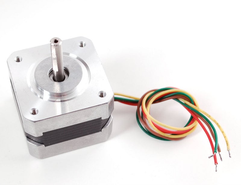
  • Up to 2 stepper motors (unipolar or bipolar) with single coil, double coil, interleaved or micro-stepping.
  • Motors automatically disabled on power-up
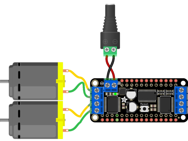
  • Big 3.5mm terminal block connectors to easily hook up wires (18-26AWG) and power
  • Polarity protected 2-pin terminal block and jumper to connect external power, for separate logic/motor supplies
  • Completely stackable design: 5 address-select jumper pads means up to 32 stackable wings: that's 64 steppers or 128 DC motors! What on earth could you do with that many steppers? I have no idea but if you come up with something send us a photo because that would be a pretty glorious project.
  • Download the easy-to-use Arduino software library, check out the examples and you're ready to go!

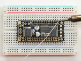
Comes with an assembled & tested FeatherWing, terminal blocks & plain header. Some soldering is required to assemble the headers on. Stacking headers not included, but we sell them in the shop so if you want to stack shields, please pick them up at the same time. Feather and motors are not included but we have lots of motors in the shop. You can use any DC or stepper motors that run from 4.5-13.5VDC and draw under 1.2A per coil. You'll likely also need to provide some external power supply for your motors, since its not suggested you run motors from the Feather's lipoly battery.

Motor Power Pins

You must provide an external power supply for driving the motors. Provide 5-12V DC power + ground on these pins! Soldering in a terminal block will make it a little easier to swap in power supplies

Motor Outputs

There are two motor sets. The left set is known as Stepper 1 or M1 + M2. The right set is Stepper 2 or M3 + M4

You can control 2 Steppers, or 1 Stepper + up to 2 DC motors or up to 4 DC motors by mixing and matching what is connected to each port.

Logic Power Pins

The logic power to the I2C expander and motor pins comes from the Feather's 3.3V regulator, 3.3V and ground are both required.

I2C Data Pins

All data and control is done over I2C so it works with any and all Feathers! No need to set any PWMs. SDA and SCL are highlighted above. There are 10K pullups to 3.3V on each.

I2C Addressing

You can stack multiple Motor Wings. Each board in the chain must be assigned a unique address. This is done with the address jumpers on the bottom of the board. The I2C base address for each board is 0x60. The binary address that you program with the address jumpers is added to the base I2C address.

To program the address offset, use a drop of solder to bridge the corresponding address jumper for each binary '1' in the address.

The left-most jumper is address bit #0, then to the right of that is address bit #1, etc up to address bit #4

Prepare the header strip:


Cut the strip to length if necessary. It will be easier to solder if you insert it into a breadboard - long pins down

Add the FeatherWing:


Place the featherwing over the pins so that the short pins poke through the two rows of breakout pads

And Solder!


Be sure to solder all pins for reliable electrical contact.

(For tips on soldering, be sure to check out ourGuide to Excellent Soldering).

Start by soldering the first row of header

Now flip around and solder the other row completely

You're done with the two header strips.


Check your solder joints visually and continue onto the next steps

Next we will solder in the five 3.5mm terminal blocks used to connect power & the motors to the FeatherWing board. 


Make sure the open parts of the terminals face outwards so you can easily connect wires.


The terminal blocks have interlocking dovetailed grooves on the sides.  Line two of them up as shown, and press down to lock them together as a 4-position terminal block.  It is a snug fit, so you may have to press hard.


To make it easier to keep these in place, you can use some tape to hold down the two header pieces. Tacky clay also works, whatever you've got handy!


Solder in each block, make sure you get to each of the 10 pins

Now that you're done with the terminal blocks, check your work make sure that each solder joint is done and looks shiny

OK You're done! You can now plug in your FeatherWing into your Feather and get movin'

For more controlling than 4 Motors / 2 Steppers, you can stack Motor FeatherWings, but the assembly is a little different.


You'll need to grab Feather Stacking Headers from the shop

Prep the Breadboard:


Place the normal headers into the breadboard with the short side sticking up. These will help keep the Stacking Headers in place when soldering to the FeatherWing

Add the FeatherWing:


Place the stacking headers into the FeatherWing so that the long pins poke through the two rows of breakout pads. Make sure the long pins are sticking out underneath the FeatherWing

Flip it upside down so that the stacking headers fit over the headers in the breadboard


Now the headers are nicely aligned and ready to solder!

Solder!

Be sure to solder all pins for reliable electrical contact.

(For tips on soldering, be sure to check out our Guide to Excellent Soldering).

Start by soldering the first row of header

Now flip around and solder the other row completely


When you are finished, check that your soldered joints are nice and shiny. The rest of the assembly is the same as the non-stacking version.

Now you're ready to stack !

You can stack multiple Motor Featherwings to drive more steppers and DC motors - dozens of them!

Check out the Motor Shield tutorial page for how this works and code examples, its identical to the Featherwing except the jumpers are on the bottom of the PCB not to the side

Install Adafruit Motor Shield V2 library

To use the shield on an Arduino, you'll need to install the Adafruit Motorshield v2 library. This library is not compatible with the older AF_Motor library used for v1 shields. However, if you have code for the older shield, adapting the code to use the new shield isn't difficult. We had to change the interface a little to support shield stacking, & we think its worth it!

To begin controlling motors, you will need to install the Adafruit_Motor_Shield_V2_Library library (code on our github repository). It is available from the Arduino library manager so we recommend using that.

From the IDE open up the library manager...

And type in adafruit motor to locate the library. Click Install

If you plan to use AccelStepper for acceleration control or for simultaneous control of multiple stepper motors, you will also need to download and install the AccelStepper library:

Running the Example Code

DC Motor

The library comes with a few examples to get you started up fast. We suggest getting started with the DC motor example. You can use any DC motor that can be powered by 6V-12VDC

First, restart the IDE to make sure the new library is loaded.

Plug the Wing into the Feather and connect a DC motor to Motor 1 - it does not matter which wire goes into which terminal block as motors are bi-directional. Connect to the top two terminal ports. See the photo below for the red and blue wire example. Be sure to screw down the terminal blocks to make a good connection!

You must also supply 5-12VDC to power the motor. You can power the Wing via a connected DC Barrel Jack as seen above. A battery pack is good for portable use. Note that this will not power the Feather, that's normal - you want to keep separate power supplies and the Feather is best powered by a separate lipoly battery

If the Green LED next to the power terminal block isn't lit up brightly do not continue!

Once you have verified the motor is connected properly and you have the power LED lit up brightly, we can upload our code.

In the IDE, load File->Examples->Adafruit_MotorShield->DCMotorTest

You should see and hear the DC motor turn on and move back and forth, attaching a slip of paper or tape as a 'flag' can help you visualize the movement if you have trouble seeing the movement

Stepper Motor Test


You can also test a stepper motor connection with the Wing. The wing can run unipolar (5-wire and 6-wire) and bipolar (4-wire) steppers. It cannot run steppers with any other # of wires! The code is the same for unipolar or bipolar motors, the wiring is just slightly different.

Plug the Wing into the Feather and connect a stepper motor to motor port 2 - unlike DC motors, the wire order does matter. Connect to the top two terminal ports (coil #1) and the bottom two terminal ports (coil #2).

  • If you have a bipolar motor, use all 4 pins
  • If you are using a unipolar motor with 5 wires, connect the common wire to GND on the power terminal block
  • If you are using a motor with 6 wires, it can be wired for either unipolar or bipolar operation.  For best performance leave the center-tap wires unconnected for bipolar operation.  For unipolar, you can connect the two center-tap wires together to GND on the power terminal block

You must also supply 5-12VDC to power the motor. You can power the Wing via a connected DC Barrel Jack as seen above. A battery pack is good for portable use. Note that this will not power the Feather, that's normal - you want to keep separate power supplies and the Feather is best powered by a separate lipoly battery

If the Green LED next to the power terminal block isn't lit up brightly do not continue!

Once you have verified the motor is connected properly and you have the power LED lit up brightly, we can upload our code.

In the IDE, load File->Examples->Adafruit_MotorShield->StepperTest

You should see and hear the stepper motor turn on and move back and forth, attaching a slip of paper or tape as a 'flag' can help you visualize the movement if you have trouble seeing the movement. There are four ways to move a stepper, with varying speed, torque and smoothness tradeoffs. This example code will demonstrate all four.

DC motors are used for all sort of robotic projects.

The motor FeatherWing can drive up to 4 DC motors bi-directionally. That means they can be driven forwards and backwards. The speed can also be varied at 0.5% increments using the high-quality built in PWM. This means the speed is very smooth and won't vary!

Note that the H-bridge chip is not meant for driving continuous loads of 1.2A, so this is for small motors. Check the datasheet for information about the motor to verify its OK!

Connecting DC Motors

To connect a motor, simply solder two wires to the terminals and then connect them to either the M1, M2, M3, or M4. Then follow these steps in your sketch

Include the required libraries

Make sure you #include the required libraries

#include <Wire.h>
#include <Adafruit_MotorShield.h>
#include "utility/Adafruit_PWMServoDriver.h"

Create the Adafruit_MotorShield object

Adafruit_MotorShield AFMS = Adafruit_MotorShield(); 

Create the DC motor object

Request the DC motor from the Adafruit_MotorShield:

Adafruit_DCMotor *myMotor = AFMS.getMotor(1);

with getMotor(port#). Port# is which port it is connected to. If you're using M1 its 1, M2 use 2, M3 use 3 and M4 use 4

Connect to the Controller

In your setup() function, call begin() on the Adafruit_MotorShield object:

AFMS.begin();

Set default speed

Set the speed of the motor using setSpeed(speed) where the speed ranges from 0 (stopped) to 255 (full speed). You can set the speed whenever you want. Note that the PWM range is 12-bit but to maintain backwards-compatibility with analogWrite we use 8 bits only. If you really need 12-bits, you'll need to drive the PCA9685 'by hand' which is not covered here!

myMotor->setSpeed(100); 

Run the motor

To run the motor, call run(direction) where direction is FORWARD, BACKWARD or RELEASE. Of course, the Arduino doesn't actually know if the motor is 'forward' or 'backward', so if you want to change which way it thinks is forward, simply swap the two wires from the motor to the shield.

myMotor->run(FORWARD);

Stepper motors are great for (semi-)precise control, perfect for many robot and CNC projects. This motor shield supports up to 2 stepper motors. The library works identically for bi-polar and uni-polar motors

For unipolar motors: to connect up the stepper, first figure out which pins connected to which coil, and which pins are the center taps. If its a 5-wire motor then there will be 1 that is the center tap for both coils. Theres plenty of tutorials online on how to reverse engineer the coils pinout. The center taps should both be connected together to the GND terminal on the motor shield output block. then coil 1 should connect to one motor port (say M1 or M3) and coil 2 should connect to the other motor port (M2 or M4).

For bipolar motors: its just like unipolar motors except theres no 5th wire to connect to ground. The code is exactly the same.

Running a stepper is a little more intricate than running a DC motor but its still very easy

Include the required libraries

Make sure you #include the required libraries

#include <Wire.h>
#include <Adafruit_MotorShield.h>
#include "utility/Adafruit_PWMServoDriver.h"

Create the Adafruit_MotorShield object

Adafruit_MotorShield AFMS = Adafruit_MotorShield(); 

Create the stepper motor object

Request the Stepper motor from the Adafruit_MotorShield:

Adafruit_StepperMotor *myMotor = AFMS.getStepper(200, 2);

...with getStepper(steps, stepper#).

Steps indicates how many steps per revolution the motor has. A 7.5 degree/step motor has 360/7.5 = 48 steps.

Stepper# is which port it is connected to. If you're using M1 and M2, its port 1. If you're using M3 and M4 indicate port 2

Set default speed

Set the speed of the motor using setSpeed(rpm) where rpm is how many revolutions per minute you want the stepper to turn.

Run the motor

Then every time you want the motor to move, call the step(#steps, direction, steptype) procedure. #steps is how many steps you'd like it to take. direction is either FORWARD or BACKWARD and the step type is SINGLE, DOUBLE, INTERLEAVE or MICROSTEP.

  • "Single" means single-coil activation
  • "Double" means 2 coils are activated at once (for higher torque)
  • "Interleave" means that it alternates between single and double to get twice the resolution (but of course its half the speed).
  • "Microstepping" is a method where the coils are PWM'd to create smooth motion between steps.

Theres tons of information about the pros and cons of these different stepping methods in the resources page.

You can use whichever stepping method you want, changing it "on the fly" to as you may want minimum power, more torque, or more precision.

By default, the motor will 'hold' the position after its done stepping. If you want to release all the coils, so that it can spin freely, call release()

The stepping commands are 'blocking' and will return once the steps have finished.

Because the stepping commands 'block' - you have to instruct the Stepper motors each time you want them to move. If you want to have more of a 'background task' stepper control, check out AccelStepper library (install similarly to how you did with Adafruit_MotorShield) which has some examples for controlling three steppers simultaneously with varying acceleration

class Adafruit_MotorShield;

The Adafruit_MotorShield class represents a motor shield and must be instantiated before any DCMotors or StepperMotors can be used. You will need to declare one Adafruit_MotorShield for each shield in your system.

Adafruit_MotorShield(uint8_t addr = 0x60);

The constructor takes one optional parameter to specify the i2c address of the shield. The default address of the constructor (0x60) matches the default address of the boards as shipped. If you have more than one shield in your system, each shield must have a unique address.

void begin(uint16_t freq = 1600);

begin() must be called in setup() to initialize the shield. An optional frequency parameter can be used to specify something other than the default maximum: 1.6KHz PWM frequency.

Adafruit_DCMotor *getMotor(uint8_t n);

This function returns one of 4 pre-defined DC motor objects controlled by the shield. The parameter specifies the associated motor channel: 1-4.

Adafruit_StepperMotor *getStepper(uint16_t steps, uint8_t n);

This function returns one of 2 pre-defined stepper motor objects controlled by the shield.
The first parameter specifies the number of steps per revolution.
The second parameter specifies the associated stepper channel: 1-2.

void setPWM(uint8_t pin, uint16_t val);
void setPin(uint8_t pin, boolean val);

These are low-level functions to control pins on the on-board PWM driver chip. These functions are intended for internal use only.

class Adafruit_DCMotor

The Adafruit_DCMotor class represents a DC motor attached to the shield. You must declare an Adafruit_DCMotor for each motor in your system.

Adafruit_DCMotor(void);

The constructor takes no arguments. The motor object is typically initialized by assigning a motor object retrieved from the shield class as below:
// Create the motor shield object with the default I2C address
Adafruit_MotorShield AFMS = Adafruit_MotorShield(); 

// Select which 'port' M1, M2, M3 or M4. In this case, M1
Adafruit_DCMotor *myMotor = AFMS.getMotor(1);
// You can also make another motor on port M2
Adafruit_DCMotor *myOtherMotor = AFMS.getMotor(2);

void run(uint8_t);

The run() function controls the motor state. The parameter can have one of 3 values:

  • FORWARD - Rotate in a forward direction
  • BACKWARD - Rotate in the reverse direction
  • RELEASE - Stop rotation

Note that the "FORWARD" and "BACKWARD" directions are arbitrary. If they do not match the actual direction of your vehicle or robot, simple swap the motor leads.

Also note that "RELEASE" simply cuts power to the motor. It does not apply any braking.

void setSpeed(uint8_t);

The setSpeed() function controls the power level delivered to the motor. The speed parameter is a value between 0 and 255.

Note that setSpeed just controls the power delivered to the motor. The actual speed of the motor will depend on several factors, including: The motor, the power supply and the load.

class Adafruit_StepperMotor

The Adafruit_StepperMotor class represents a stepper motor attached to the shield. You must declare an Adafruit_StepperMotor for each stepper motor in your system.

Adafruit_StepperMotor(void);

The constructor takes no arguments. The stepper motor is typically initialized by assigning a stepper object retrieved from the shield as below:
// Create the motor shield object with the default I2C address
Adafruit_MotorShield AFMS = Adafruit_MotorShield(); 

// Connect a stepper motor with 200 steps per revolution (1.8 degree)
// to motor port #2 (M3 and M4)
Adafruit_StepperMotor *myMotor = AFMS.getStepper(200, 2);

void step(uint16_t steps, uint8_t dir, uint8_t style = SINGLE);

The step() function controls stepper motion.
  • The first parameter specifies how many steps to move.
  • The second parameter specifies the direction: FORWARD or BACKWARD
  • The last parameter specifies the stepping style: SINGLE, DOUBLE, INTERLEAVED or MICROSTEP
The ste() function is synchronous and does not return until all steps are complete. When complete the motor remains powered to apply "holding torque" to maintain position.

void setSpeed(uint16_t);

The setSpeed() function controls the speed of the stepper motor rotation. Speed is specified in RPM.

uint8_t onestep(uint8_t dir, uint8_t style);

The oneStep() function is a low-level internal function called by step(). But it can be useful to call on its own to implement more advanced functions such as acceleration or coordinating simultaneous movement of multiple stepper motors. The direction and style parameters are the same as for step(), but onestep() steps exactly once.

Note: Calling step() with a step count of 1 is not the same as calling onestep(). The step function has a delay based on the speed set in setSpeed(). onestep() has no delay.

void release(void);

The release() function removes all power from the motor. Call this function to reduce power requirements if holding torque is not required to maintain position.

We've written a handy CircuitPython library for the various DC Motor and Stepper kits called Adafruit CircuitPython MotorKit that handles all the complicated setup for you. All you need to do is import the appropriate class from the library, and then all the features of that class are available for use. We're going to show you how to import the MotorKit class and use it to control DC and stepper motors with the Adafruit Stepper + DC Motor FeatherWing.

CircuitPython Microcontroller and Python Wiring

First assemble the FeatherWing exactly as shown in the previous pages. There's no wiring needed to connect the FeatherWing to the Feather. The example below shows wiring two DC motors to the FeatherWing once it has been attached to a Feather using the stacking assembly method. You'll want to connect a barrel jack to the power terminal to attach an appropriate external power source to the FeatherWing. The FeatherWing will not function without an external power source!

  • Connect the two motor wires from the first motor to the M1 terminal on the FeatherWing.
  • Connect the two motor wires from the second motor to the M2 terminal on the FeatherWing.
  • Connect the positive side of the power terminal to the positive side of the barrel jack.
  • Connect the negative side of the power terminal to the negative side of the barrel jack.

CircuitPython Installation of MotorKit and Necessary Libraries

You'll need to install a few libraries on your Feather board.

First make sure you are running the latest version of Adafruit CircuitPython for your board.

Next you'll need to install the necessary libraries to use the hardware--carefully follow the steps to find and install these libraries from Adafruit's CircuitPython library bundle.  Our CircuitPython starter guide has a great page on how to install the library bundle.

If you choose, you can manually install the libraries individually on your board:

  • adafruit_pca9685
  • adafruit_bus_device
  • adafruit_register
  • adafruit_motor
  • adafruit_motorkit

Before continuing make sure your board's lib folder or root filesystem has the adafruit_pca9685.mpy, adafruit_register, adafruit_motor, adafruit_bus_device and adafruit_motorkit files and folders copied over.

Next connect to the board's serial REPL so you are at the CircuitPython >>> prompt.

CircuitPython Usage

To demonstrate the usage, we'll initialise the library and use Python code to control DC and stepper motors from the board's Python REPL.

First you'll need to import, initialize the MotorKit class and provide the I2C device.

import board
from adafruit_motorkit import MotorKit
kit = MotorKit(i2c=board.I2C())

You can also initialise the library without specifying I2C as follows:

from adafruit_motorkit import MotorKit
kit = MotorKit()

DC Motors

The four motor spots on the FeatherWing are available as motor1, motor2, motor3, and motor4.

In this example we'll use motor1.

Note: For small DC motors like sold in the shop you might run into problems with electrical noise they generate and erratic behavior on your board.  The SAMD21 Feather M0 boards in particular have been susceptible to this issue.  If you see erratic behavior like the motor not spinning or the board resetting at high motor speeds this is likely the problem. See this motor guide FAQ page for information on capacitors you can solder to the motor to reduce noise.

Now to move a motor you can set the throttle attribute. We don't call it speed because it doesn't correlate to a particular number of revolutions per minute (RPM). RPM depends on the motor and the voltage which is unknown.

For example to drive motor M1 forward at a full speed you set it to 1.0:

kit.motor1.throttle = 1.0

To run the motor at half throttle forward use a decimal:

kit.motor1.throttle = 0.5

Or to reverse the direction use a negative throttle:

kit.motor1.throttle = -0.5

You can stop the motor with a throttle of 0:

kit.motor1.throttle = 0

To let the motor coast and then spin freely set throttle to None.

kit.motor1.throttle = None

That's all there is to controlling DC motors with CircuitPython!  With DC motors you can build fun moving projects like robots or remote controlled cars that glide around with ease.

Stepper Motors

Similar DC motors, stepper motors are available as stepper1 and stepper2. stepper1 is made up of the M1 and M2 terminals, and stepper2 is made up of the M3 and M4 terminals.

We'll use stepper1 in our example.

The most basic function (and the default) is to do one single coil step.

kit.stepper1.onestep()

You can also call the onestep function with two optional keyword arguments. To use these, you'll need to import stepper as well.

from adafruit_motor import stepper

Then you have access to the following options:

  • direction, which should be one of the following constant values:
    • stepper.FORWARD (default)
    • stepper.BACKWARD.
  • style, which should be one of the values:
    • stepper.SINGLE (default) for a full step rotation to a position where one single coil is powered
    • stepper.DOUBLE for a full step rotation to position where two coils are powered providing more torque
    • stepper.INTERLEAVE for a half step rotation interleaving single and double coil positions and torque
    • stepper.MICROSTEP for a microstep rotation to a position where two coils are partially active.
  • release() which releases all the coils so the motor can free spin, and also won't use any power

The function returns the current step 'position' in microsteps which can be handy to understand how far the stepper has moved, or you can ignore the result.

To take a double-coil step backward call:

kit.stepper1.onestep(direction=stepper.BACKWARD, style=stepper.DOUBLE)

You can even use a loop to continuously call onestep and move the stepper, for example a loop of 200 microsteps forward for smooth movement:

for i in range(200):
    kit.stepper1.onestep(style=stepper.MICROSTEP)

That's all there is to controlling a stepper motor from CircuitPython!  Steppers are handy motors for when you need smooth or precise control of something--for example 3D printers and CNC machines use steppers to precisely move tools around surfaces.

Using MotorKit with Multiple I2C Devices

Using multiple I2C devices with MotorKit is super simple. The important thing is how you instantiate the other I2C devices.

This example shows how to use the APDS9960 gesture and proximity sensor along with MotorKit. The following will work with any other I2C device as well.

First import all of the necessary libraries.

import board
from adafruit_motorkit import MotorKit
from adafruit_apds9960.apds9960 import APDS9960

Next, create an I2C object, and instantiate the two libraries.

i2c = board.I2C()
kit = MotorKit(i2c=i2c)
apds = APDS9960(i2c)

From there you can use both MotorKit and the APDS9960 sensor however you'd like in your code!

This will work with any I2C sensor. Simply import the appropriate library, and instantiate the I2C object and the library.

That's all there is to using multiple I2C devices with MotorKit!

Full Example Code

For DC motors:

# SPDX-FileCopyrightText: 2021 ladyada for Adafruit Industries
# SPDX-License-Identifier: MIT

"""Simple test for using adafruit_motorkit with a DC motor"""
import time
import board
from adafruit_motorkit import MotorKit

kit = MotorKit(i2c=board.I2C())

kit.motor1.throttle = 1.0
time.sleep(0.5)
kit.motor1.throttle = 0

For stepper motors:

# SPDX-FileCopyrightText: 2021 ladyada for Adafruit Industries
# SPDX-License-Identifier: MIT

"""Simple test for using adafruit_motorkit with a stepper motor"""
import time
import board
from adafruit_motorkit import MotorKit

kit = MotorKit(i2c=board.I2C())

for i in range(100):
    kit.stepper1.onestep()
    time.sleep(0.01)

Schematic

Click to embiggen

Fabrication Print

Dimensions in Inches

This guide was first published on Jul 29, 2016. It was last updated on Apr 13, 2024.