This RFID tag is really unique: it works with mobile phones just like other RFID tags, but you can reprogram it over I2C. The tag shows up as an ISO/IEC 15693 (13.56MHz) chip which is readable by phones and tablets. This could be interesting in situations where you want a tag that can be re-written dynamically when connected to a controller. For example, we did a test where we had a microcontroller write different URLs a few seconds apart, and the mobile phone detected the different URLs one after the other.

Note that the most popular hobby RFID reader/writer chips like the PN532 do not support ISO15693 so you cannot use those to read the ST25DV tag once programmed! We used both Apple and Android phones with success to read the tags.

According to the datasheet, one can even use it as a 'I2C to RFID' transfer system to wirelessly send and receive data from mobile devices (you'll need to write a custom app for that kind of project, though).

ST has written a handy library that you can easily use to write NFC URLs to the chip over I2C. You cannot use an Arduino UNO (ATmega328p) with the ST25DV library, there's not enough RAM. Please use a Metro M0 or other SAMD chip (or better) to communicate with the ST25DV.  There's no Python or CircuitPython library for this chip at this time, only Arduino.

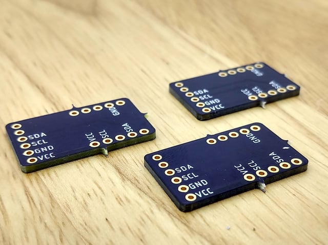
To make connections easy, our breakout contains an ST25DV04 chip, support circuitry and even a PCB trace antenna. There's standard 0.100”/ 2.54mm pitch headers for use with a breadboard. Should you wish to avoid soldering, the breakout also includes our Stemma QT connectors (SparkFun Qwiic compatible). Using these handy connectors you can simply plug in the sensor and get rolling with your project.

Power Pins

  • Vin - The chip can safely run from 3-5VDC. To power the board, give it the same power as the logic level of your microcontroller - e.g. for a 5V microcontroller like Arduino, use 5V
  • GND - common ground for power and logic

I2C Logic Pins:

  • SCL - This is the I2C clock pin SCL, connect to your microcontroller's I2C clock line. There's a 10K pullup on this pin.
  • SDA - This is the I2C data pin SDA, connect to your microcontroller's I2C data line. There's a 10K pullup on this pin.
  • STEMMA QT - These connectors allow you to connect to dev boards with STEMMA QT connectors or to other things with various associated accessories

Other Pins:

  • GPO - General Purpose Output pin. This is a configurable output pin used to provide RF activity information to an external device. Note: Requires an external pullup resistor (> 4.7 KΩ) to operate. The interrupt consists in pulling the state to a low level or outputting a low-level pulse on GPO pin.
  • VEH - This analog output pin is used to deliver the analog voltage VEH available when the Energy harvesting mode is enabled and if the RF field strength is sufficient. Note: Energy harvesting voltage output is not regulated.
ST's library will not run an Arduino UNO (ATmega328 or ATmega32u4) - you need a chip with more memory like SAMD, ST, ESP chips

Using the ST25DV16K breakout with Arduino is a simple matter of wiring up the sensor to your Arduino-compatible microcontroller, installing the ST25DV library they've written, and running the provided example code.

I2C Wiring

Use this wiring to connect via I2C interface. The ST25DV is one device but responds to THREE I2C addresses: 0x2D, 0x53 (user memory) and 0x57 (system memory)

  • Connect board VIN (red wire) to Arduino 5V if you are running a 5V board Arduino (Mega, etc.). If your board is 3V, connect to that instead.
  • Connect board GND (black wire) to Arduino GND
  • Connect board SCL (yellow wire) to Arduino SCL
  • Connect board SDA (blue wire) to Arduino SDA

Here is how to wire the sensor to a board using a solderless breadboard:

  • Connect board VIN (red wire) to Arduino 5V if you are running a 5V board Arduino (Mega, etc.). If your board is 3V, connect to that instead.
  • Connect board GND (black wire) to Arduino GND
  • Connect board SCL (yellow wire) to Arduino SCL
  • Connect board SDA (blue wire) to Arduino SDA

Library Installation

You can install the ST32Duino ST25DV library for Arduino using the Library Manager in the Arduino IDE.

Click the Manage Libraries ... menu item, search for ST25DV , and select the STM32duino ST25DV library:

Load Example

Open up File -> Examples -> STM32duino ST25DV -> ST25DV_HelloWorld

You'll need to define the pins, regardless of whether you're using them. The section below requires a set of pins.

Update this section to the following:

#else
// Please define the pin and wire instance used for your board
#define GPO_PIN A1
#define LPD_PIN A2
#define SDA_PIN D4
#define SCL_PIN D5

If you'd like, scroll down to setup() and you can modify the URL written to the tag

If you're using a microcontroller with native USB (which many are) we recommend adding the line

while (!SerialPort) delay(10);

after

// Initialize serial for output.
SerialPort.begin(115200);

So that you'll see the error report or success when the serial console is opened (otherwise you can miss it)

Now upload! You can open the serial console for debug information. Once programmed, you can scan the tag with your phone - the tag does not need to be powered to be scanned, it acts like a 'normal' RFID tag. Since the antenna's a little small you will need to physically tap the tag.

This guide was first published on Aug 10, 2020. It was last updated on Mar 08, 2024.