Ding dong! Hear that? It's the PiCowbell ringing, letting you know that the new Adafruit PiCowbell Adalogger is in stock and ready to assist your Raspberry Pi Pico and Pico W project with handy hardware and datalogging.

The PiCowbell Adalogger is the same size and shape as a Pico and is intended to socket underneath to make your next data logging or data reading project super easy. Micro SD card socket? Yes! STEMMA QT / Qwiic connector for fast I2C? Indeed. Real Time Clock with battery backup for accurate timekeeping? Of course!

Please Note! There are a lot of possible configurations, and we stock various headers depending on how you want to solder and attach. Especially if you want the Pico on top so that the BOOTSEL button and LED are accessible.

  1. Use the Pico Stacking Headers if you want to be able to plug into a breadboard or other accessory with sockets.
  2. Use the Pico Socket Headers if you want to plug directly in and have a nice solid connection that doesn't have any poking-out-bits.
  3. Use the Short Socket Headers for a very slim but pluggable design; note that you'll want to trim down the Pico's headers or use the short plug headers on the Pico to have a skinny sandwich.
  4. Solder the PCB directly to the Pico headers - of course, this is very compact and inexpensive, but you won't be able to remove the PiCowbell.

The PiCowbell Adalogger provides you with:

  • Right angle JST SH connector for I2C / Stemma QT / Qwiic connection. Provides 3V, GND, IO4 (SDA), and IO5 (SCL).
  • MicroSD card holder for adding as much storage as you could possibly want for reading or writing. Connected to SPI pins 16, 18, 19 and card select on 17. Optional card detect line can be connected to pin 15.
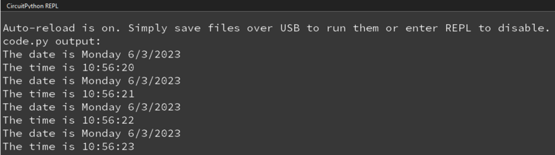
  • PCF8523 Real Time Clock with CR1220 Coin cell backup for many years of timekeeping. Set the time once using our example sketches and then you can data-log with accurate timestamps. Uses I2C.
  • Reset button- Press to restart your program.
  • Many pads on the Adalogger have a duplicate hole pad next to it for solder-jumpering.
  • The ground pads have white silkscreen rectangles to easily identify.
  • Gold-plated pads for easy soldering.

If using the Philhower Arduino core, the Wire peripheral is already set up to use IO4 and IO5. If using CircuitPython or MicroPython, you'll need to let the code know to look at 4+5 for SDA+SCL pins.

Does not come with a micro SD card or a coin cell battery. A CR1220 coin cell is required to use the RTC battery-backup capabilities! We don't include one by default to make shipping easier for those abroad, but we do stock them, so pick one up or use any CR1220 you have handy.

The default I2C address for the PCF8523 RTC module is 0x68.

Power

  • VB (VBUS) - This is the micro-USB input voltage, connected to the micro-USB port on the Raspberry Pi Pico. It is nominally 5V.
  • VS (VSYS) - This is the main system input voltage. It can range from 1.8V to 5.5V and is used to generate the 3.3V needed for the RP2040 and the GPIO pins.
  • EN (3V3_EN) - This connects to the enable pin on the Raspberry Pi Pico, and is pulled high (to VSYS) via a 100kΩ resistor.
  • 3V - This is the 3.3V output from the Raspberry Pi Pico. 
  • VR (ADC_VREF) - This is the ADC power supply and reference voltage. It is generated on the Raspberry Pi Pico by filtering the 3.3V supply. It can be used with an external reference when ADC performance is required.
  • G - This is the common ground for power and logic. All GND pins are highlighted in white on the silk, with the exception of the ground pins on either side of the SD card slot. They are labeled G.

I2C Logic

  • SCL - I2C clock pin on the PiCowbell. It is connected to your microcontroller I2C clock line, which is GPIO5 on the Pico. This connection is shared with the STEMMA QT port on the end of the board.
  • SDA - I2C data pin on the PiCowbell. It is connected to your microcontroller I2C data line, which is GPIO4 on the Pico. This connection is shared with the STEMMA QT port on the end of the board.
  • STEMMA QT - These connectors allow you to connect to dev boards with STEMMA QT connectors or to other things with various associated accessories. There's one port at the end that connects to your microcontroller. The other four connectors in two rows of two are discussed below.

Duplicate GPIO Hole Pads

The following pads on the PiCowbell Adalogger have a duplicate hole pad next to it for solder-jumpering:

  • GP0-GP11, GP20-GP22, Reset, A0-A2, VR, 3V, EN, VS and VB. Ground pins that have a duplicate hole pad are highlighted in white on the silk.

microSD Card SPI

The microSD card slot is connected to the following pins for SPI:

  • MI (MISO/GP16) - This is the SPI MISO (Microcontroller In / Serial Out) pin. It's used for the SD card to send data to the microcontroller.
  • SCK (GP18) - This is the SPI clock input pin.
  • MO (MOSI/GP19) - This is the SPI MOSI (Microcontroller Out / Serial In) pin. It is used to send data from the microcontroller to the SD card.
  • CS (Chip Select/GP17) - This is the chip select pin for the SD card.

SD Detect Jumper

On the back of the board, directly above GP15 and to the left of the cowbell logo on the silk, is the SD Detect jumper. The jumper is labeled SD Det on the silk.

You can solder this jumper closed to connect the optional SD card detect line to GP15.

Coin Cell Battery Holder

In the center of the PiCowbell is a holder for a CR1220 coin cell battery. Slot in a CR1220 battery into the holder to use the PCF8523 RTC battery-backup capabilities.

A CR1220 coin cell is required to use the RTC battery-backup capabilities!
Angled shot of CR1220 12mm Diameter - 3V Lithium Coin Cell Battery - CR1220.
These are the highest quality & capacity batteries, the same as shipped with the iCufflinks, iNecklace, Datalogging and GPS Shields, GPS HAT, etc. One battery per order...
$0.95
In Stock

Reset Button

In the center of the board, to the left of the coin cell battery holder, is the reset button. It is labeled RST on the board silk. You can press it to restart your program.

Although these pages show the PiCowbell Proto, the soldering instructions are applicable for all PiCowbell boards.

There are four ways to get your PiCowbell board working with your Pico. To keep things flexible, PiCowbells do not come with headers: there's a lot of possible configurations and we stock various headers depending on how you want to solder and attach. Especially since you want the Pico on top, so that the BOOTSEL button and LED are accessible.

The options are as follows.

  1. Use the Pico Stacking Headers if you want to be able to plug into a breadboard or other accessory with sockets.
  2. Use the Pico Socket Headers if you want to plug directly into the Pico and have a nice solid connection that doesn't have any poking-out-bits.
  3. For some PiCowbells: Use the Short Socket Headers for a very slim but pluggable design, note that you'll want to trim down the Pico's headers or use the short plug headers on the Pico to have a skinny sandwich.
  4. For some PiCowbells: Solder the PiCowbell directly to the standard headers already soldered to your Pico. Of course this is very compact and inexpensive but you won't be able to remove the PiCowbell. However, this method is not possible for some PiCowbell variants depending on the clearance of the components on the PiCowbell (i.e. the PiCowbell Adalogger and its coin cell battery holder).

The next page shows how to solder standard headers onto a Pico board. The following four pages walk you through each type of PiCowbell assembly so you can choose the one that will work best for you!

You MUST solder all of the pins for the PiCowbell to work! Soldering only a few pins, or not soldering at all are not sufficient!

If you're unsure about soldering up the Pico and PiCowbell, check out our FAQ on soldering.

Three out of four of the assembly methods included in this guide assume you have a Raspberry Pi Pico soldered up with standard male headers in preparation for using it with the PiCowbell Proto. This page will show you how to solder a set of standard headers to a Pico.

(The shorty header assembly method uses short male headers on the Pico. The soldering concept is exactly the same, but use the shorty male headers on the Pico instead of standard ones. You can follow these instructions with the shorty headers and you'll be set for that.)

Follow the steps below to solder the standard male headers to a Pico. The process is the same for all flavors of Pico, such as Pico W.

Assembly Steps

Use the Pico to line up the headers on a breadboard. This is the easiest way to ensure the headers are soldered on straight. 

Solder the pins on each end of the two header strips, so the four corners of the Pico are soldered. This ensures the Pico and headers are attached properly while you continue to solder the rest of the pins.

Solder the rest of the pins.

Remove it from the breadboard. You're done! 

For a bit more detail on the process of soldering standard male headers to a board, check out the How to Solder Headers' Male Headers page.

The first PiCowbell assembly method uses stacking headers, which allows you to use a breadboard with your PiCowbell-Pico sandwich. This is super helpful when you're still prototyping other parts of your project, or simply want jumper-wire access to the Pico pins in addition to the PiCowbell.

This page assumes you have already soldered standard male headers to your Pico. If you have not, please return to the Pico assembly page and follow the steps there.

Follow the steps below to solder stacking headers to your PiCowbell.

Although these pages show the PiCowbell Proto, the soldering instructions are applicable for all PiCowbell boards.

Assembly Steps

Place a standard-header-soldered Pico upside down on the table, so the long side of the header pins are facing up. Press the female sockets of each stacking header onto one of the rows of standard headers attached to the Pico, until they are fully attached. 

Ensure the PiCowbell is oriented correctly before beginning assembly. The PiCowbell should be top-down, so that you are looking at the bottom of the PiCowbell. The STEMMA QT connector should be on the same end as the Pico USB connector, and the reset button should be on the opposite end with the Pico debug pins.

The PiCowbell pins must match the pinout on the Pico.

Remember, the pins are labeled on the bottom of the Pico. In this case, that works well because they are labeled on both sides of the PiCowbell, allowing for direct comparison before attaching the PiCowbell to the stacking header assembly.

Ensure the PiCowbell is oriented properly before beginning soldering! If you solder it on upside down or backwards, it will not function properly!

Press the PiCowbell onto the male pins sticking up from the stacking headers. You may need to push the stacking header pins in or out a bit to get the PiCowbell attached.

With the stacking header male pins sticking up, the bottom of the PiCowbell should be facing up as well.

Solder the pins on each end of each stacking header, so that the opposite four corners of the PiCowbell are soldered on.

Solder the rest of the pins onto the PiCowbell. 

You're done! Now you can attach the whole sandwich to a breadboard, have access to the pins via the breadboard, and still be able to use the PiCowbell as well.

This PiCowbell assembly method uses female socket headers on the PiCowbell to create a standalone sandwich when attached to a Pico with standard male headers. 

This page assumes you have already soldered standard male headers to your Pico. If you have not, please return to the Pico assembly page and follow the steps there.

Follow the steps below to solder socket headers to your PiCowbell.

Although these pages show the PiCowbell Proto, the soldering instructions are applicable for all PiCowbell boards.

Assembly Steps

Place a standard-header-soldered Pico upside down on the table, so the long side of the header pins are facing up. Press the female sockets onto one of the rows of standard headers attached to the Pico, until both are fully attached. 

Ensure the PiCowbell is oriented correctly before beginning assembly. The PiCowbell should be top-down, so that you are looking at the bottom of the Cowbell. The STEMMA QT connector should be on the same end as the Pico USB connector, and the reset button should be on the opposite end with the Pico debug pins.

The PiCowbell pins must match the pinout on the Pico.

Remember, the pins are labeled on the bottom of the Pico. In this case, that works well because they are labeled on both sides of the PiCowbell, allowing for direct comparison before attaching the PiCowbell to the stacking header assembly.

Ensure the PiCowbell is oriented properly before beginning soldering! If you solder it on upside down or backwards, it will not function properly!

Press the PiCowbell onto the pins sticking up from the socket headers. You may need to push the stacking header pins in or out a bit to get the PiCowbell attached.

Solder the pins on each end of each socket header, so that the opposite four corners of the PiCowbell are soldered on.

Solder the rest of the pins onto the PiCowbell.

That's it, you're done! 

This PiCowbell assembly method uses shorty female socket headers on the PiCowbell to create a standalone sandwich when attached to a Pico with shorty male headers. 

This page assumes you have already soldered shorty male headers to your Pico. If you have not, please return to the Pico assembly page and follow the steps there. The page shows how to solder standard male headers to the Pico, but the concept is identical with the shorty headers.

Follow the steps below to solder shorty socket headers to your PiCowbell.

Although these pages show the PiCowbell Proto, the soldering instructions are applicable for all PiCowbell boards.

Assembly Steps

Solder the short male headers to the Pico. See the Pico assembly page for instructions on soldering headers to the Pico.

Place a shorty-header-soldered Pico upside down (headers up) on the table. Press the each of the short female sockets onto one of the rows of short headers attached to the Pico, until both are fully attached.

Ensure the PiCowbell is oriented correctly before beginning assembly. The PiCowbell should be top-down, so that you are looking at the bottom of the Cowbell. The STEMMA QT connector should be on the same end as the Pico USB connector, and the reset button should be on the opposite end with the Pico debug pins.

The PiCowbell pins must match the pinout on the Pico.

Remember, the pins are labeled on the bottom of the Pico. In this case, that works well because they are labeled on both sides of the PiCowbell, allowing for direct comparison before attaching the Cowbell to the stacking header assembly.

Ensure the PiCowbell is oriented properly before beginning soldering! If you solder it on upside down or backwards, it will not function properly!

Press the PiCowbell onto the pins sticking up from the shorty female headers. You may need to push the shorty header pins in or out a bit to get the PiCowbell attached.

Solder the pins on each end of each female header, so that the opposite four corners of the PiCowbell are soldered on.

Try not to use too much solder on these four pins! The solder can wick into the associated female header socket, onto the inserted male pin, and permanently attach the two boards.

Do not use too much solder when tacking the four corners! It can wick into the female header and permanently attach the two boards!

CAREFULLY remove the partially soldered PiCowbell from the Pico, before continuing to solder the rest of the PiCowbell pins.

As stated above, too much solder on the shorty female header pins can wick into the associated header socket, onto the inserted male pin, and permanently attach the two boards.

Solder the rest of the pins onto the PiCowbell. Be sure to keep the shorty female headers square while you solder the rest of the pins.

Press the PiCowbell onto the Pico to attach the two boards. Make sure you've oriented it correctly!

The STEMMA QT connector should be on the same end as the Pico USB connector, and the reset button should be on the opposite end with the Pico debug pins.

That's it! You're done!

Before using the real time clock (RTC) for the first time on the PiCowbell Adalogger, you need to calibrate it by setting the time with the code.py file below. After setting the time, the RTC module will use the coin cell battery to keep time even when you unplug the PiCowbell from the Raspberry Pi Pico.

Begin by inserting a CR1220 coin cell battery into the PiCowbell Adalogger battery holder. Then, attach the PiCowbell to a Pico or Pico W as described in the assembly pages.

Angled shot of CR1220 12mm Diameter - 3V Lithium Coin Cell Battery - CR1220.
These are the highest quality & capacity batteries, the same as shipped with the iCufflinks, iNecklace, Datalogging and GPS Shields, GPS HAT, etc. One battery per order...
$0.95
In Stock
A CR1220 coin cell is required to use the RTC battery-backup capabilities!

CircuitPython Usage

To use with CircuitPython, you need to first install the Adafruit_CircuitPython_PCF8523 module, and its dependencies, into the lib folder on your CIRCUITPY drive. Then you need to update code.py with the example script.

Thankfully, we can do this in one go. In the example below, click the Download Project Bundle button below to download the necessary libraries and the code.py file in a zip file. Extract the contents of the zip file.

Connect your Pico + PiCowbell sandwich to your computer via a known good USB data+power cable. Your board should show up as a thumb drive named CIRCUITPY in your File Explorer or Finder (depending on your operating system). Copy the entire lib folder and the code.py file to your CIRCUITPY drive.

Your CIRCUITPY/lib folder should contain the following folders and files:

  • /adafruit_bus_device
  • /adafruit_register
  • adafruit_pcf8523.mpy
CIRCUITPY

Code

Once everything is saved to the CIRCUITPY drive, connect to the serial console to see the data printed out!

# SPDX-FileCopyrightText: 2017 ladyada for Adafruit Industries
# SPDX-License-Identifier: MIT

import time
import board
import busio
from adafruit_pcf8523.pcf8523 import PCF8523

I2C = busio.I2C(board.GP5, board.GP4)
rtc = PCF8523(I2C)

days = ("Sunday", "Monday", "Tuesday", "Wednesday", "Thursday", "Friday", "Saturday")

set_time = False

if set_time:   # change to True if you want to write the time!
    #                     year, mon, date, hour, min, sec, wday, yday, isdst
    t = time.struct_time((2023,  3,   6,   10,  55,  00,    1,   -1,    -1))
    # you must set year, mon, date, hour, min, sec and weekday
    # yearday is not supported, isdst can be set but we don't do anything with it at this time

    print("Setting time to:", t)     # uncomment for debugging
    rtc.datetime = t
    print()

while True:
    t = rtc.datetime
    #print(t)     # uncomment for debugging

    print("The date is %s %d/%d/%d" % (days[t.tm_wday], t.tm_mon, t.tm_mday, t.tm_year))
    print("The time is %d:%02d:%02d" % (t.tm_hour, t.tm_min, t.tm_sec))

    time.sleep(1) # wait a second

Setting the time

The first time you run the program, you'll need to set the time

find these lines:

set_time = False

if set_time:   # change to True if you want to write the time!
    #                     year, mon, date, hour, min, sec, wday, yday, isdst
    t = time.struct_time((2023,  3,   6,   11,  05,  00,    1,   -1,    -1))
    # you must set year, mon, date, hour, min, sec and weekday
    # yearday is not supported, isdst can be set but we don't do anything with it at this time

Change the set_time in the first line to be True:

set_time = True

and update the time.struct_time to have the current time starting from year to weekday. The last two entries can stay at -1

Re-run the sketch by saving and you'll see this out of the REPL:

Note the part where the program says it is Setting time to:

Now you can go back and change set_time to False:

set_time = False

and save, so you don't reset the RTC again.

The code will now output the time and date.

As of CircuitPython 9, a mount point (folder) named /sd is required on the CIRCUITPY drive. Make sure to create that directory after upgrading CircuitPython.

The following example code will show you how use the PiCowbell Adalogger with CircuitPython to log data from a sensor to a file on an SD card with timestamps from the RTC module. In addition to a Raspberry Pi Pico and PiCowbell Adalogger, you will also need:

  • CR1220 coin cell battery
  • microSD card
  • STEMMA QT cable
  • MCP9808 Temperature Sensor
Angled shot of CR1220 12mm Diameter - 3V Lithium Coin Cell Battery - CR1220.
These are the highest quality & capacity batteries, the same as shipped with the iCufflinks, iNecklace, Datalogging and GPS Shields, GPS HAT, etc. One battery per order...
$0.95
In Stock
Hand removing/installing micro SD card from SD adapter
Add mega-storage in a jiffy using this 8 GB class 4 micro-SD card. It comes with a SD adapter so you can use it with any of our shields or adapters. Preformatted to FAT so it works out...
$9.95
In Stock
Angled of of JST SH 4-Pin Cable.
This 4-wire cable is 50mm / 1.9" long and fitted with JST SH female 4-pin connectors on both ends. Compared with the chunkier JST PH these are 1mm pitch instead of 2mm, but...
$0.95
In Stock
Top view of temperature sensor breakout above an OLED display FeatherWing. The OLED display reads "MCP9808 Temp: 24.19ºC"
The MCP9808 digital temperature sensor is one of the more accurate/precise we've ever seen, with a typical accuracy of ±0.25°C over the sensor's -40°C to...
$4.95
In Stock
The following example assumes that you followed along with the RTC with CircuitPython page in this guide to set the time on the RTC module.

CircuitPython Microcontroller Wiring

Connect the Raspberry Pi Pico and PiCowbell Adalogger as described in the assembly pages. Next, insert a CR1220 battery into the coin cell battery holder on the PiCowbell Adalogger. Then, insert a microSD card into the PiCowbell Adalogger microSD card slot.

Finally, connect the MCP9808 STEMMA QT board to the PiCowbell Adalogger STEMMA QT port with a STEMMA QT cable.

CircuitPython Usage

To use with CircuitPython, you need to first install the necessary libraries into the lib folder on your CIRCUITPY drive. Then you need to update code.py with the example script.

Thankfully, we can do this in one go. In the example below, click the Download Project Bundle button below to download the necessary libraries and the code.py file in a zip file. Extract the contents of the zip file, and copy the entire lib folder and the code.py file to your CIRCUITPY drive.

Your CIRCUITPY/lib folder should contain the following folders and files:

  • /adafruit_bus_device
  • /adafruit_register
  • adafruit_mcp9808.mpy
  • adafruit_pcf8523.mpy
CIRCUITPY

Example Code

# SPDX-FileCopyrightText: 2023 Liz Clark for Adafruit Industries
#
# SPDX-License-Identifier: MIT
"""CircuitPython PiCowbell Adalogger Example"""
import time
import board
import sdcardio
import busio
import storage
import adafruit_mcp9808
from adafruit_pcf8523.pcf8523 import PCF8523

#  setup for Pico I2C
i2c = busio.I2C(board.GP5, board.GP4)
# setup for mcp9808 temp monitor
mcp9808 = adafruit_mcp9808.MCP9808(i2c)
# setup for RTC
rtc = PCF8523(i2c)

#  list of days to print to the text file on boot
days = ("Monday", "Tuesday", "Wednesday", "Thursday", "Friday", "Saturday", "Sunday")

# SPI SD_CS pin
SD_CS = board.GP17

#  SPI setup for SD card
spi = busio.SPI(board.GP18, board.GP19, board.GP16)
sdcard = sdcardio.SDCard(spi, SD_CS)
vfs = storage.VfsFat(sdcard)
try:
    storage.mount(vfs, "/sd")
    print("sd card mounted")
except ValueError:
    print("no SD card")

#  to update the RTC, change set_clock to True
#  otherwise RTC will remain set
#  it should only be needed after the initial set
#  if you've removed the coincell battery
set_clock = False

if set_clock:
    #                     year, mon, date, hour, min, sec, wday, yday, isdst
    t = time.struct_time((2023,  3,   6,   00,  00,  00,    0,   -1,    -1))

    print("Setting time to:", t)
    rtc.datetime = t
    print()

#  variable to hold RTC datetime
t = rtc.datetime

time.sleep(1)

def get_temp(sensor):
    temperature_celsius = sensor
    temperature_fahrenheit = temperature_celsius * 9 / 5 + 32
    return temperature_fahrenheit

#  initial write to the SD card on startup
try:
    with open("/sd/temp.txt", "a") as f:
        #  writes the date
        f.write('The date is {} {}/{}/{}\n'.format(days[t.tm_wday], t.tm_mon, t.tm_mday, t.tm_year))
        #  writes the start time
        f.write('Start time: {}:{}:{}\n'.format(t.tm_hour, t.tm_min, t.tm_sec))
        #  headers for data, comma-delimited
        f.write('Temp,Time\n')
        #  debug statement for REPL
        print("initial write to SD card complete, starting to log")
except ValueError:
    print("initial write to SD card failed - check card")

while True:
    try:
        #  variable for RTC datetime
        t = rtc.datetime
        #  append SD card text file
        with open("/sd/temp.txt", "a") as f:
            #  read temp data from mcp9808
            temp = get_temp(mcp9808.temperature)
            #  write temp data followed by the time, comma-delimited
            f.write('{},{}:{}:{}\n'.format(temp, t.tm_hour, t.tm_min, t.tm_sec))
            print("data written to sd card")
        #  repeat every 30 seconds
        time.sleep(30)
    except ValueError:
        print("data error - cannot write to SD card")
        time.sleep(10)

Once everything is saved to the CIRCUITPY drive, connect to the serial console to see status information from the code.

In the example, the microSD card is mounted and the file temp.txt is created to log temperature data from the MCP9808. Then in the loop, a temperature reading is taken and saved to temp.txt, along with the timestamp from the RTC module, every 30 seconds. Every time data is written to the file, data written to the sd card is written to the REPL to let you know that the code is running properly.

After logging data to the file, you can open temp.txt from the microSD card to see your data.

Talking to the RTC

The RTC is an I2C device, which means it uses 2 wires to to communicate. These two wires are used to set the time and retrieve it.

For the RTC library, we'll be using a fork of JeeLab's excellent RTC library, which is available on GitHub. You can do that by visiting the github repo and manually downloading or, easier go to the Arduino Library Manager

Type in RTClib - and find the one that is by Adafruit and click Install

There are a few different 'forks' of RTClib, make sure you are using the ADAFRUIT one!

First RTC test

The first thing we'll demonstrate is a test sketch that will read the time from the RTC once a second. We'll also show what happens if you remove the battery and replace it since that causes the RTC to halt. So to start, remove the battery from the holder while the PiCowbell is not powered or plugged into USB. Wait 3 seconds and then replace the battery. This resets the RTC chip. Now load up the matching sketch for your RTC

Open up Examples->RTClib->pcf8523

Upload it to your Pico connected to the PiCowbell Adalogger, as described in the assembly pages in this guide.

Now open up the Serial Console and make sure the baud rate is set correctly at 57600 baud you should see the following:

Whenever the RTC chip loses all power (including the backup battery) it will reset to an earlier date and report the time as 0:0:0 or similar. Whenever you set the time, this will kickstart the clock ticking.

So, basically, the upshot here is that you should never ever remove the battery once you've set the time. You shouldn't have to and the battery holder is very snug so unless the board is crushed, the battery won't 'fall out'

Setting the time

With the same sketch loaded, uncomment the line that starts with RTC.adjust like so:

  if (! rtc.initialized()) {
    Serial.println("RTC is NOT running!");
    // following line sets the RTC to the date & time this sketch was compiled
    rtc.adjust(DateTime(F(__DATE__), F(__TIME__)));

This line is very cute, what it does is take the Date and Time according the computer you're using (right when you compile the code) and uses that to program the RTC. If your computer time is not set right you should fix that first. Then you must press the Upload button to compile and then immediately upload. If you compile and then upload later, the clock will be off by that amount of time.

Then open up the Serial monitor window to show that the time has been set

From now on, you won't have to ever set the time again: the battery will last 5 or more years

Reading the time

Now that the RTC is merrily ticking away, we'll want to query it for the time. Let's look at the sketch again to see how this is done

void loop () {
    DateTime now = rtc.now();
    
    Serial.print(now.year(), DEC);
    Serial.print('/');
    Serial.print(now.month(), DEC);
    Serial.print('/');
    Serial.print(now.day(), DEC);
    Serial.print(" (");
    Serial.print(daysOfTheWeek[now.dayOfTheWeek()]);
    Serial.print(") ");
    Serial.print(now.hour(), DEC);
    Serial.print(':');
    Serial.print(now.minute(), DEC);
    Serial.print(':');
    Serial.print(now.second(), DEC);
    Serial.println();

There's pretty much only one way to get the time using the RTClib, which is to call now(), a function that returns a DateTime object that describes the year, month, day, hour, minute and second when you called now().

There are some RTC libraries that instead have you call something like RTC.year() and RTC.hour() to get the current year and hour. However, there's one problem where if you happen to ask for the minute right at 3:14:59 just before the next minute rolls over, and then the second right after the minute rolls over (so at 3:15:00) you'll see the time as 3:14:00 which is a minute off. If you did it the other way around you could get 3:15:59 - so one minute off in the other direction.

Because this is not an especially unlikely occurance - particularly if you're querying the time pretty often - we take a 'snapshot' of the time from the RTC all at once and then we can pull it apart into day() or second() as seen above. It's a tiny bit more effort but we think its worth it to avoid mistakes!

We can also get a 'timestamp' out of the DateTime object by calling unixtime which counts the number of seconds (not counting leapseconds) since midnight, January 1st 1970

    Serial.print(" since 2000 = ");
    Serial.print(now.unixtime());
    Serial.print("s = ");
    Serial.print(now.unixtime() / 86400L);
    Serial.println("d");

Since there are 60*60*24 = 86400 seconds in a day, we can easily count days since then as well. This might be useful when you want to keep track of how much time has passed since the last query, making some math a lot easier (like checking if it's been 5 minutes later, just see if unixtime() has increased by 300, you don't have to worry about hour changes)

The following example code will show you how use the PiCowbell Adalogger with Arduino to log data from a sensor to a file on an SD card with timestamps from the RTC module. In addition to a Raspberry Pi Pico and PiCowbell Adalogger, you will also need:

  • CR1220 coin cell battery
  • microSD card
  • STEMMA QT cable
  • MCP9808 Temperature Sensor
Angled shot of CR1220 12mm Diameter - 3V Lithium Coin Cell Battery - CR1220.
These are the highest quality & capacity batteries, the same as shipped with the iCufflinks, iNecklace, Datalogging and GPS Shields, GPS HAT, etc. One battery per order...
$0.95
In Stock
Hand removing/installing micro SD card from SD adapter
Add mega-storage in a jiffy using this 8 GB class 4 micro-SD card. It comes with a SD adapter so you can use it with any of our shields or adapters. Preformatted to FAT so it works out...
$9.95
In Stock
Angled of of JST SH 4-Pin Cable.
This 4-wire cable is 50mm / 1.9" long and fitted with JST SH female 4-pin connectors on both ends. Compared with the chunkier JST PH these are 1mm pitch instead of 2mm, but...
$0.95
In Stock
Top view of temperature sensor breakout above an OLED display FeatherWing. The OLED display reads "MCP9808 Temp: 24.19ºC"
The MCP9808 digital temperature sensor is one of the more accurate/precise we've ever seen, with a typical accuracy of ±0.25°C over the sensor's -40°C to...
$4.95
In Stock
The following example assumes that you followed along with the RTC with Arduino page to set the time with the RTC module and install the RTClib library.

Wiring

Connect the Raspberry Pi Pico and PiCowbell Adalogger as described in the assembly pages. Next, insert a CR1220 battery into the coin cell battery holder on the PiCowbell Adalogger. Then, insert a microSD card into the PiCowbell Adalogger microSD card slot.

Finally, connect the MCP9808 STEMMA QT board to the PiCowbell Adalogger STEMMA QT port with a STEMMA QT cable.

Library Installation

You can install the Adafruit MCP9808 library for Arduino using the Library Manager in the Arduino IDE.

Click the Manage Libraries ... menu item, search for Adafruit MCP9808 and select the Adafruit MCP9808 library:

If asked about dependencies, click "Install all".

If the "Dependencies" window does not come up, then you already have the dependencies installed. 

If the dependencies are already installed, you must make sure you update them through the Arduino Library Manager before loading the example!

Example Code

// SPDX-FileCopyrightText: 2023 Liz Clark for Adafruit Industries
//
// SPDX-License-Identifier: MIT

const int _MISO = 16;
const int _MOSI = 19;
const int _CS = 17;
const int _SCK = 18;

#include <SPI.h>
#include <SD.h>
#include <Wire.h>
#include "Adafruit_MCP9808.h"
#include "RTClib.h"

RTC_PCF8523 rtc;

char daysOfTheWeek[7][12] = {"Sunday", "Monday", "Tuesday", "Wednesday", "Thursday", "Friday", "Saturday"};

// Create the MCP9808 temperature sensor object
Adafruit_MCP9808 tempsensor = Adafruit_MCP9808();

File logfile;

// blink out an error code
void error(uint8_t errno) {
  while(1) {
    uint8_t i;
    for (i=0; i<errno; i++) {
      digitalWrite(LED_BUILTIN, HIGH);
      delay(100);
      digitalWrite(LED_BUILTIN, LOW);
      delay(100);
    }
    for (i=errno; i<10; i++) {
      delay(200);
    }
  }
}

void setup() {
  
  Serial.begin(115200);
  while (!Serial);
  Serial.println("\r\nPiCowbell Adalogger Test");

  // Ensure the SPI pinout the SD card is connected to is configured properly
  SPI.setRX(_MISO);
  SPI.setTX(_MOSI);
  SPI.setSCK(_SCK);
  
  pinMode(LED_BUILTIN, OUTPUT);

  if (!tempsensor.begin(0x18)) {
    Serial.println("Couldn't find MCP9808! Check your connections and verify the address is correct.");
    while (1);
  }
  Serial.println("Found MCP9808!");

  tempsensor.setResolution(3);

  if (! rtc.begin()) {
    Serial.println("Couldn't find RTC");
    Serial.flush();
    while (1) delay(10);
  }

  if (! rtc.initialized() || rtc.lostPower()) {
    Serial.println("RTC is NOT initialized, let's set the time!");
    // When time needs to be set on a new device, or after a power loss, the
    // following line sets the RTC to the date & time this sketch was compiled
    rtc.adjust(DateTime(F(__DATE__), F(__TIME__)));
    // This line sets the RTC with an explicit date & time, for example to set
    // January 21, 2014 at 3am you would call:
    // rtc.adjust(DateTime(2014, 1, 21, 3, 0, 0));
    //
    // Note: allow 2 seconds after inserting battery or applying external power
    // without battery before calling adjust(). This gives the PCF8523's
    // crystal oscillator time to stabilize. If you call adjust() very quickly
    // after the RTC is powered, lostPower() may still return true.
  }

  // When time needs to be re-set on a previously configured device, the
  // following line sets the RTC to the date & time this sketch was compiled
  // rtc.adjust(DateTime(F(__DATE__), F(__TIME__)));
  // This line sets the RTC with an explicit date & time, for example to set
  // January 21, 2014 at 3am you would call:
  // rtc.adjust(DateTime(2014, 1, 21, 3, 0, 0));

  // When the RTC was stopped and stays connected to the battery, it has
  // to be restarted by clearing the STOP bit. Let's do this to ensure
  // the RTC is running.
  rtc.start();

  float drift = 43; // seconds plus or minus over oservation period - set to 0 to cancel previous calibration.
  float period_sec = (7 * 86400);  // total obsevation period in seconds (86400 = seconds in 1 day:  7 days = (7 * 86400) seconds )
  float deviation_ppm = (drift / period_sec * 1000000); //  deviation in parts per million (μs)
  float drift_unit = 4.34; // use with offset mode PCF8523_TwoHours
  // float drift_unit = 4.069; //For corrections every min the drift_unit is 4.069 ppm (use with offset mode PCF8523_OneMinute)
  int offset = round(deviation_ppm / drift_unit);
  // rtc.calibrate(PCF8523_TwoHours, offset); // Un-comment to perform calibration once drift (seconds) and observation period (seconds) are correct
  // rtc.calibrate(PCF8523_TwoHours, 0); // Un-comment to cancel previous calibration

  Serial.print("Offset is "); Serial.println(offset); // Print to control offset

  // see if the card is present and can be initialized:
  if (!SD.begin(_CS)) {
    Serial.println("initialization failed!");
    return;
  }
  Serial.println("initialization done.");
}

void loop() {
  tempsensor.wake();
  DateTime now = rtc.now();
  float c = tempsensor.readTempC();
  float f = tempsensor.readTempF();
  Serial.println("Writing to SD card");
  digitalWrite(LED_BUILTIN, HIGH);

// make a string for assembling the data to log:
  String dataString = "";

  dataString += "The current temp is: ";
  dataString += String(c);
  dataString += "C, ";
  dataString += String(f);
  dataString += "F, at ";
  dataString += String(now.year(), DEC);
  dataString += String('/');
  dataString += String(now.month(), DEC);
  dataString += String('/');
  dataString += String(now.day(), DEC);
  dataString += String(" (");
  dataString += String(daysOfTheWeek[now.dayOfTheWeek()]);
  dataString += String(") ");
  dataString += String(now.hour(), DEC);
  dataString += String(':');
  dataString += String(now.minute(), DEC);
  dataString += String(':');
  dataString += String(now.second(), DEC);


  // open the file. note that only one file can be open at a time,
  // so you have to close this one before opening another.
  File dataFile = SD.open("datalog.txt", FILE_WRITE);

  // if the file is available, write to it:
  if (dataFile) {
    dataFile.println(dataString);
    dataFile.close();
    // print to the serial port too:
    Serial.println(dataString);
  }
  // if the file isn't open, pop up an error:
  else {
    Serial.println("error opening datalog.txt");
  }
  digitalWrite(LED_BUILTIN, LOW);
  
  delay(5000);
}

Upload the sketch to your board and open up the Serial Monitor (Tools -> Serial Monitor) at 115200 baud. You'll see the setup run with confirmation messages that the MCP9808 has been found over I2C and the microSD card has been initialized properly. As data is written to the microSD card, you'll see the message "Writing to SD card" appear in the Serial Monitor, along with the temperature reading and timestamp from the RTC. The onboard LED on the Raspberry Pi Pico will also light-up when a write is in progress.

After logging data to the file on the microSD card, you can open datalog.txt from the microSD card to see your data.

This guide was first published on Mar 07, 2023. It was last updated on Apr 16, 2024.