Wiring
If you have a STEMMA QT breakout cable, then you can wire like this:

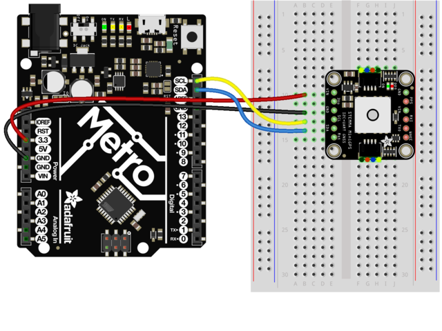
If you want to solder pins to the header connectors and use a breadboard, then wire like this:
Installation
The Adafruit GPS Library includes support for the Mini GPS PA1010D module. You can install it from the Arduino IDE via the Library Manager:

Click the Manage Libraries... menu item, search for Adafruit GPS, and select the Adafruit GPS Library:

Echo Test Demo
We can test basic functionality using one of the examples from the library. This won't do any parsing. It simply dumps the raw data sentences as received from the GPS module.
Open up File -> Examples -> Adafruit GPS Library -> GPS_I2C_EchoTest and upload to your Arduino board with the GPS module connected.
Once the sketch is uploaded, open up the Serial Monitor (Tools -> Serial Monitor) at 115200 baud. You should see something like this:

If you see this, then you are successfully talking to the GPS module. Once it obtains a lock on the GPS satellites, which can takes several minutes, there will be more information in the sentences. To see that information in a more user friendly format, try running the GPS_I2C_Parsing example from the library.


