

Overview
Folks love our wide selection of RGB matrices and accessories for making custom colorful LED displays... and our RGB Matrix Shields and FeatherWings can be quickly soldered together to make the wiring much easier. But what if we made it even easier than that? Like, no solder, no wiring, just instant plug-and-play? Dream no more - with the Adafruit Matrix Portal S3 add-on for RGB Matrices, there's never been an easier way to create powerful Internet-connected LED displays.

You can plug directly into the back of any HUB-75 compatible display (all the ones we stock will work) from 16x32 up to 64x64 or use the stock 2x8 IDC cables to plug into the front. Further matrix panels can be chained together. Use the included screws to attach the power cable to the power plugs with a common screwdriver, then power it with any USB C power supply. Chain dozens of displays for long stretches, or you can panelize them in a grid for bigger displays. For larger projects, power the matrices with a separate 5V power adapter.

Then code up your project in CircuitPython or Arduino, our Protomatter matrix library works great on the ESP32-S3 chipset, knowing that you've got the wiring and level shifting all handled. Here's what you get:
- ESP32-S3 processor, 8 MB flash, 2 MB of PSRAM, with full Arduino or CircuitPython support
- WiFi and Bluetooth LE baked right in, full Arduino support. CircuitPython only supports WiFi at this time, not BLE on the S3 chip.
- USB Type C connector for data and power connectivity
- I2C STEMMA QT connector for plug-n-play use of any of our STEMMA QT devices or sensors can also be used with any Grove I2C devices using this adapter cable
- JST 3-pin connector that also has analog input for quick connection with any JST PH 2.0mm pitch cable.
- LIS3DH accelerometer for digital sand projects or detecting taps/orientation.
- GPIO breakout strip - has reset, boot selection, TX debug output, and 6 GPIO including 4 analog inputs with PWM, SPI, or I2S support for adding other hardware.
- Address E line jumper for use with 64x64 matrices (check your matrix to see which pin is used for address E, we default to pin 8
- Two user interface buttons + one reset button
- Indicator NeoPixel and red LED
- Green power indicator LEDs for both 3V and 5V power
- 2x10 socket connector fits snugly into 2x8 HUB75 ports without worrying about 'off by one' errors
- 2x8 IDC plug connector works with standard cables that come with matrices.

The Matrix Portal uses an Espressif ESP32-S3 Wi-Fi+BLE chipset, and has dropped the SAMD51 from the original Matrix Portal due to silicon shortages. But turns out the S3 is really great at doing all the work of the original all on its own:
- The S3 has a parallel output drive peripheral which means that controlling the matrix is done without bitbanging.
- The S3 has two cores so one can be dedicated to WiFi networking or matrix control while the other runs your code.
- With native USB, its easy to have it act like a keyboard, or mouse, or MIDI device and it also has plenty of I2C, SPI, I2S, UART and analog inputs.
- Lots of memory: 8MB of Flash means plenty of space for code, files, GIFs and more. 2MB of PSRAM means you can read and parse a lot of IoT data and still have plenty of RAM for the matrix display buffers.
- The only real thing missing from the original Matrix Portal is the S3 does not have an analog output DAC pin, we recommend an I2S amplifier for audio instead.
Comes with one fully programmed and assembled MatrixPortal, preprogrammed with a basic display demo for 32x64 LED matrices.

Page last edited June 11, 2025
Pinouts


There are so many great features on the Adafruit MatrixPortal S3. Let's take a look at what's available!

The main processor chip is the Espressif ESP32-S3 with 3.3v logic/power. It has 8MB of Flash and 2MB of RAM.
The ESP32-S3 comes with WiFi and Bluetooth LE baked right in, though CircuitPython only supports WiFi at this time, not BLE on the S3 chip.


There is a 2x8 pin HUB75 plug connector on the reverse side that plugs directly into the HUB75 port on your RGB Matrix. The socket itself is 2x10 so that it fits snug and lined up in a 2x8 IDC socket. Otherwise its easy to get it 'off by one'
There is also a 2x8 pin HUB75 socket connector on the component side that allows you the option to instead connect a 2x8 IDC cable to your RGB Matrix.

There are +5V and Ground M3-threaded screw terminals on either side of the HUB75 connector. These provide power to the RGB Matrix.
If you would like to power the RGB Matrix with external power, we recommend disconnecting it from here and providing power directly to the matrix.
These terminals were designed as outputs ONLY - power from the USB port connects directly to these pads, so you should power from USB and then connect the matrix power inputs to these terminals.
While it's technically possible to power the MatrixPortal through here, we strongly discourage that because plugging anything into the USB port at the same time could result in damage.

The MatrixPortal S3 includes a LIS3DH Triple-Axis Accelerometer. The accelerometer is connected via the I2C bus.
Please note the address of the accelerometer is 0x19 not 0x18 which is the default in our libraries.

There is a 4-pin Stemma QT connector on the left. The I2C has pullups to 3.3V power and is connected to the LIS3DH already.
In CircuitPython, you can use the STEMMA connector with board.SCL and board.SDA, or board.STEMMA_I2C().

3V is the output from the 3.3V regulator, it can supply 500mA peak.
GND is the common ground for all power and logic.

RESET is the Reset pin. Tie to ground to manually reset the ESP32-S3.
Tying BOOT to ground while resetting will place the ESP32-S3 in ROM bootloader mode.

If you'd like to do lower level debugging, we have the ESP32-S3's TXD0 debug pin exposed to view messages.
To read, you would connect a Serial UART cable's Receive connection here and the cable's ground connection to the GND pin.

The TXO pin and RXI pin are for serial communication with the ESP32-S3 microcontroller and can be used to connect various peripherals such as a GPS.
The RXI pin is attached to board.RX and Arduino 8 and the TXO pin is attached to board.TX and Arduino 18.
Both of these pins can be used for digital I/O.

On the bottom side towards the right, there is a connector labeled A0. This is a 3-pin JST analog connector for sensors, NeoPixels, digital input/output, or analog input.
For the JST connected, there is a jumper above that can be cut and soldered to use 3V instead of 5V.
Along the bottom there are also pins labeled A1 through A4.
All of these pins can be used for analog inputs or digital I/O.

There are two LEDs on the board controllable through programming.
There is the RGB status NeoPixel labeled "NeoPixel". It is connected to board.NEOPIXEL or Arduino 4
As well, there is the D13 LED. This is attached to board.LED and Arduino 13

There is one USB port on the board.
On the left side, towards the bottom, is a USB Type C port, which is used for powering and programming both the board and RGB Matrix.

There are three buttons along the left side of the MatrixPortal S3.
The reset button is located in the top position. Click it once to re-start your firmware. Click it again while the NeoPixel is Purple to enter bootloader mode.
The up button is located in the middle and is attached to board.BUTTON_UP and Arduino 6.
The down button is located on the bottom and is attached to board.BUTTON_DOWN and Arduino 7.
The up and down buttons do not have any pull-up resistors connected to them and pressing either of them pulls the input low.
The boot button is located between the up button and the Microcontroller. Hold it while pressing reset to enter ROM Bootloader mode.

This jumper is used for use with 64x64 matrices and is either connected to pin 8 or pin 16 of the HUB75 connector. Check your matrix to see which pin is used for address E.
You can close the jumper by using your soldering iron to melt a blob of solder on the bottom solder jumper so the middle pad is 'shorted' to 8. (This is compatible with 64x64 matrices in the Adafruit store. For 64x64 matrices from other sources, you might need to use 16 instead, check the datasheet of your display.)
Page last edited June 11, 2025
Prep the MatrixPortal


Power Prep
The MatrixPortal supplies power to the matrix display panel via two standoffs. These come with protective tape applied (part of our manufacturing process) which MUST BE REMOVED!
Use some tweezers or a fingernail to remove the two amber circles.


Power Terminals
Next, screw in the spade connectors to the corresponding standoff.
- red wire goes to +5V
- black wire goes to GND


Panel Power
Plug either one of the four-conductor power plugs into the power connector pins on the panel. The plug can only go in one way, and that way is marked on the board's silkscreen.
Dual Matrix Setup
If you're planning to use a 64x64 matrix, follow these instructions on soldering the Address E Line jumper.


Board Connection
Now, plug the board into the left side shrouded 8x2 connector as shown. The orientation matters, so take a moment to confirm that the white indicator arrow on the matrix panel is oriented pointing up and right as seen here and the MatrixPortal overhangs the edge of the panel when connected. This allows you to use the edge buttons from the front side.
Check nothing is impeding the board from plugging in firmly. If there's a plastic nub on the matrix that's keeping the Portal from sitting flat, cut it off with diagonal cutters


Page last edited June 11, 2025
LED Matrix Diffuser

LED Diffusion Acrylic
You can add an LED diffusion acrylic faceplate to the your LED matrix display. (Pictured here with the ON AIR project)
This can help protect the LEDs as well as enhance the look of the sign both indoors and out by reducing glare and specular highlights of the plastic matrix grid.


Measure and Cut the Plastic
You can use the sign to measure and mark cut lines on the paper backing of the acrylic sheet.
Then, use a tablesaw or bandsaw with a fine toothed blade and a guide or sled to make the cuts.
Note: it is possible to score and snap acrylic, but it can be very tricky to get an even snap without proper clamping.


Peel away the paper backing from both sides and set the acrylic onto your matrix display with the matte finished side facing out.


Uglu Dashes
The best method we've found for adhering acrylic to the matrix display is to use Uglu Dashes clear adhesive rectangles from Pro Tapes. They are incredibly strong (although can be removed if necessary), easy to apply, and are invisible once attached.
Use one at each corner and one each at the halfway point of the long edges, then press the acrylic and matrix panel together for about 20 seconds.
Here you can see the impact of using the diffusion acrylic. (Pictured here with the ON AIR sign project)


Stand
A very simple and attractive way to display your matrix is with the adjustable bent-wire stand.

Alternately, you can use a frame, 3D printed brackets, tape, glue, or even large binder clips to secure the acrylic to the sign and then mount it on on a wall, shelf, or display cabinet.
These mini-magnet feet can be used to stick the sign to a ferrous surface.
Page last edited June 11, 2025
Install CircuitPython
CircuitPython is a derivative of MicroPython designed to simplify experimentation and education on low-cost microcontrollers. It makes it easier than ever to get prototyping by requiring no upfront desktop software downloads. Simply copy and edit files on the CIRCUITPY drive to iterate.
Set up CircuitPython Quick Start!
Follow this quick step-by-step for super-fast Python power :)
Further Information
For more detailed info on installing CircuitPython, check out Installing CircuitPython.

Click the link above and download the latest UF2 file.
Download and save it to your desktop (or wherever is handy).

Plug your MatrixPortal S3 into your computer using a known-good USB cable.
A lot of people end up using charge-only USB cables and it is very frustrating! So make sure you have a USB cable you know is good for data sync.
Click the Reset button (indicated by the green arrow) on your board. When you see the NeoPixel RGB LED (indicated by the magenta arrow) turn purple, press it again. At that point, the NeoPixel should turn green. If it turns red, check the USB cable, try another USB port, etc.
If double-clicking doesn't work the first time, try again. Sometimes it can take a few tries to get the rhythm right!

You will see a new disk drive appear called MATRXS3BOOT.
Drag the adafruit_circuitpython_etc.uf2 file over to MATRXS3BOOT.

Page last edited June 11, 2025
What is CircuitPython?
CircuitPython is a programming language designed to simplify experimenting and learning to program on low-cost microcontroller boards. It makes getting started easier than ever with no upfront desktop downloads needed. Once you get your board set up, open any text editor, and get started editing code. It's that simple.

CircuitPython is based on Python
Python is the fastest growing programming language. It's taught in schools and universities. It's a high-level programming language which means it's designed to be easier to read, write and maintain. It supports modules and packages which means it's easy to reuse your code for other projects. It has a built in interpreter which means there are no extra steps, like compiling, to get your code to work. And of course, Python is Open Source Software which means it's free for anyone to use, modify or improve upon.
CircuitPython adds hardware support to all of these amazing features. If you already have Python knowledge, you can easily apply that to using CircuitPython. If you have no previous experience, it's really simple to get started!

CircuitPython is designed to run on microcontroller boards. A microcontroller board is a board with a microcontroller chip that's essentially an itty-bitty all-in-one computer. The board you're holding is a microcontroller board! CircuitPython is easy to use because all you need is that little board, a USB cable, and a computer with a USB connection. But that's only the beginning.
Other reasons to use CircuitPython include:
- You want to get up and running quickly. Create a file, edit your code, save the file, and it runs immediately. There is no compiling, no downloading and no uploading needed.
- You're new to programming. CircuitPython is designed with education in mind. It's easy to start learning how to program and you get immediate feedback from the board.
- Easily update your code. Since your code lives on the disk drive, you can edit it whenever you like, you can also keep multiple files around for easy experimentation.
- The serial console and REPL. These allow for live feedback from your code and interactive programming.
- File storage. The internal storage for CircuitPython makes it great for data-logging, playing audio clips, and otherwise interacting with files.
- Strong hardware support. CircuitPython has builtin support for microcontroller hardware features like digital I/O pins, hardware buses (UART, I2C, SPI), audio I/O, and other capabilities. There are also many libraries and drivers for sensors, breakout boards and other external components.
- It's Python! Python is the fastest-growing programming language. It's taught in schools and universities. CircuitPython is almost-completely compatible with Python. It simply adds hardware support.
This is just the beginning. CircuitPython continues to evolve, and is constantly being updated. Adafruit welcomes and encourages feedback from the community, and incorporate it into the development of CircuitPython. That's the core of the open source concept. This makes CircuitPython better for you and everyone who uses it!
Page last edited June 11, 2025
CircuitPython Internet Test
One of the great things about most Espressif microcontrollers are their built-in WiFi capabilities. This page covers the basics of getting connected using CircuitPython.
The first thing you need to do is update your code.py to the following (it will error until WiFi details are added). Click the Download Project Bundle button to download the necessary libraries and the code.py file in a zip file. Extract the contents of the zip file, and copy the entire lib folder and the code.py file to your CIRCUITPY drive.
# SPDX-FileCopyrightText: 2020 Brent Rubell for Adafruit Industries
#
# SPDX-License-Identifier: MIT

import os
import ipaddress
import ssl
import wifi
import socketpool
import adafruit_requests

# URLs to fetch from
TEXT_URL = "http://wifitest.adafruit.com/testwifi/index.html"
JSON_QUOTES_URL = "https://www.adafruit.com/api/quotes.php"
JSON_STARS_URL = "https://api.github.com/repos/adafruit/circuitpython"

print("ESP32-S2 WebClient Test")

print(f"My MAC address: {[hex(i) for i in wifi.radio.mac_address]}")

print("Available WiFi networks:")
for network in wifi.radio.start_scanning_networks():
    print("\t%s\t\tRSSI: %d\tChannel: %d" % (str(network.ssid, "utf-8"),
                                             network.rssi, network.channel))
wifi.radio.stop_scanning_networks()

print(f"Connecting to {os.getenv('CIRCUITPY_WIFI_SSID')}")
wifi.radio.connect(os.getenv("CIRCUITPY_WIFI_SSID"), os.getenv("CIRCUITPY_WIFI_PASSWORD"))
print(f"Connected to {os.getenv('CIRCUITPY_WIFI_SSID')}")
print(f"My IP address: {wifi.radio.ipv4_address}")

ping_ip = ipaddress.IPv4Address("8.8.8.8")
ping = wifi.radio.ping(ip=ping_ip)

# retry once if timed out
if ping is None:
    ping = wifi.radio.ping(ip=ping_ip)

if ping is None:
    print("Couldn't ping 'google.com' successfully")
else:
    # convert s to ms
    print(f"Pinging 'google.com' took: {ping * 1000} ms")

pool = socketpool.SocketPool(wifi.radio)
requests = adafruit_requests.Session(pool, ssl.create_default_context())

print(f"Fetching text from {TEXT_URL}")
response = requests.get(TEXT_URL)
print("-" * 40)
print(response.text)
print("-" * 40)

print(f"Fetching json from {JSON_QUOTES_URL}")
response = requests.get(JSON_QUOTES_URL)
print("-" * 40)
print(response.json())
print("-" * 40)

print()

print(f"Fetching and parsing json from {JSON_STARS_URL}")
response = requests.get(JSON_STARS_URL)
print("-" * 40)
print(f"CircuitPython GitHub Stars: {response.json()['stargazers_count']}")
print("-" * 40)

print("Done")
Your CIRCUITPY drive should resemble the following.

To get connected, the next thing you need to do is update the settings.toml file.
The settings.toml File
We expect people to share tons of projects as they build CircuitPython WiFi widgets. What we want to avoid is people accidentally sharing their passwords or secret tokens and API keys. So, we designed all our examples to use a settings.toml file, that is on your CIRCUITPY drive, to hold secret/private/custom data. That way you can share your main project without worrying about accidentally sharing private stuff.
If you have a fresh install of CircuitPython on your board, the initial settings.toml file on your CIRCUITPY drive is empty.
To get started, you can update the settings.toml on your CIRCUITPY drive to contain the following code.
# SPDX-FileCopyrightText: 2023 Adafruit Industries
#
# SPDX-License-Identifier: MIT

# This is where you store the credentials necessary for your code.
# The associated demo only requires WiFi, but you can include any
# credentials here, such as Adafruit IO username and key, etc.
CIRCUITPY_WIFI_SSID = "your-wifi-ssid"
CIRCUITPY_WIFI_PASSWORD = "your-wifi-password"
This file should contain a series of Python variables, each assigned to a string. Each variable should describe what it represents (say wifi_ssid), followed by an = (equals sign), followed by the data in the form of a Python string (such as "my-wifi-password" including the quote marks).
At a minimum you'll need to add/update your WiFi SSID and WiFi password, so do that now!
As you make projects you may need more tokens and keys, just add them one line at a time. See for example other tokens such as one for accessing GitHub or the Hackaday API. Other non-secret data like your timezone can also go here.
For the correct time zone string, look at http://worldtimeapi.org/timezones and remember that if your city is not listed, look for a city in the same time zone, for example Boston, New York, Philadelphia, Washington DC, and Miami are all on the same time as New York.
Of course, don't share your settings.toml - keep that out of GitHub, Discord or other project-sharing sites.
If you connect to the serial console, you should see something like the following:

In order, the example code...
Checks the ESP32's MAC address.
print(f"My MAC address: {[hex(i) for i in wifi.radio.mac_address]}")
Performs a scan of all access points and prints out the access point's name (SSID), signal strength (RSSI), and channel.
print("Available WiFi networks:")
for network in wifi.radio.start_scanning_networks():
    print("\t%s\t\tRSSI: %d\tChannel: %d" % (str(network.ssid, "utf-8"),
                                             network.rssi, network.channel))
wifi.radio.stop_scanning_networks()
Connects to the access point you defined in the settings.toml file, and prints out its local IP address.
print(f"Connecting to {os.getenv('WIFI_SSID')}")
wifi.radio.connect(os.getenv("WIFI_SSID"), os.getenv("WIFI_PASSWORD"))
print(f"Connected to {os.getenv('WIFI_SSID')}")
print(f"My IP address: {wifi.radio.ipv4_address}")
Attempts to ping a Google DNS server to test connectivity. If a ping fails, it returns None. Initial pings can sometimes fail for various reasons. So, if the initial ping is successful (is not None), it will print the echo speed in ms. If the initial ping fails, it will try one more time to ping, and then print the returned value. If the second ping fails, it will result in "Ping google.com: None ms" being printed to the serial console. Failure to ping does not always indicate a lack of connectivity, so the code will continue to run.
ping_ip = ipaddress.IPv4Address("8.8.8.8")
ping = wifi.radio.ping(ip=ping_ip) * 1000
if ping is not None:
    print(f"Ping google.com: {ping} ms")
else:
    ping = wifi.radio.ping(ip=ping_ip)
    print(f"Ping google.com: {ping} ms")
The code creates a socketpool using the wifi radio's available sockets. This is performed so we don't need to re-use sockets. Then, it initializes a a new instance of the requests interface - which makes getting data from the internet really really easy.
pool = socketpool.SocketPool(wifi.radio)
requests = adafruit_requests.Session(pool, ssl.create_default_context())
To read in plain-text from a web URL, call requests.get - you may pass in either a http, or a https url for SSL connectivity.
print(f"Fetching text from {TEXT_URL}")
response = requests.get(TEXT_URL)
print("-" * 40)
print(response.text)
print("-" * 40)
Requests can also display a JSON-formatted response from a web URL using a call to requests.get.
print(f"Fetching json from {JSON_QUOTES_URL}")
response = requests.get(JSON_QUOTES_URL)
print("-" * 40)
print(response.json())
print("-" * 40)
Finally, you can fetch and parse a JSON URL using requests.get. This code snippet obtains the stargazers_count field from a call to the GitHub API.
print(f"Fetching and parsing json from {JSON_STARS_URL}")
response = requests.get(JSON_STARS_URL)
print("-" * 40)
print(f"CircuitPython GitHub Stars: {response.json()['stargazers_count']}")
print("-" * 40)
OK you now have your ESP32 board set up with a proper settings.toml file and can connect over the Internet. If not, check that your settings.toml file has the right SSID and password and retrace your steps until you get the Internet connectivity working!
IPv6 Networking
Starting in CircuitPython 9.2, IPv6 networking is available on most Espressif wifi boards. Socket-using libraries like adafruit_requests and adafruit_ntp will need to be updated to use the new APIs and for now can only connect to services on IPv4.
IPv6 connectivity & privacy
IPv6 addresses are divided into many special kinds, and many of those kinds (like those starting with FC, FD, FE) are private or local; Addresses starting with other prefixes like 2002: and 2001: are globally routable. In 2024, far from all ISPs and home networks support IPv6 internet connectivity. For more info consult resources like Wikipedia. If you're interested in global IPv6 connectivity you can use services like Hurricane Electric to create an "IPv6 tunnel" (free as of 2024, but requires expertise and a compatible router or host computer to set up)
It's also important to be aware that, as currently implemented by Espressif, there are privacy concerns especially when these devices operate on the global IPv6 network: The device's unique identifier (its EUI-64 or MAC address) is used by default as part of its IPv6 address. This means that the device identity can be tracked across multiple networks by any service it connects to.
Enable IPv6 networking
Due to the privacy consideration, IPv6 networking is not automatically enabled. Instead, it must be explicitly enabled by a call to start_dhcp_client with the ipv6=True argument specified:
wifi.start_dhcp_client(ipv6=True)
Check IP addresses
The read-only addresses property of the wifi.radio object holds all addresses, including IPv4 and IPv6 addresses:
>>> wifi.radio.addresses
('FE80::7EDF:A1FF:FE00:518C', 'FD5F:3F5C:FE50:0:7EDF:A1FF:FE00:518C', '10.0.3.96')
The wifi.radio.dns servers can be IPv4 or IPv6:
>>> wifi.radio.dns
('FD5F:3F5C:FE50::1',)
>>> wifi.radio.dns = ("1.1.1.1",)
>>> wifi.radio.dns
('1.1.1.1',)
>>> wifi.radio.ping("google.com")
0.043
>>> wifi.radio.ping("ipv6.google.com")
0.048
Create & use IPv6 sockets
Use the address family socket.AF_INET6. After the socket is created, use methods like connect, send, recfrom_into, etc just like for IPv4 sockets. This code snippet shows communicating with a private-network NTP server; this IPv6 address will not work on your network:
>>> ntp_addr = ("fd5f:3f5c:fe50::20e", 123)
>>> PACKET_SIZE = 48
>>>
>>> buf = bytearray(PACKET_SIZE)
>>> with socket.socket(socket.AF_INET6, socket.SOCK_DGRAM) as s:
...     s.settimeout(1)
...     buf[0] = 0b0010_0011
...     s.sendto(buf, ntp_addr)
...     print(s.recvfrom_into(buf))
...     print(buf)
...
48
(48, ('fd5f:3f5c:fe50::20e', 123))
bytearray(b'$\x01\x03\xeb\x00\x00\x00\x00\x00\x00\x00GGPS\x00\xeaA0h\x07s;\xc0\x00\x00\x00\x00\x00\x00\x00\x00\xeaA0n\xeb4\x82-\xeaA0n\xebAU\xb1')
Page last edited June 11, 2025
MatrixPortal Library Overview
The MatrixPortal library was inspired by the PyPortal library, but a slightly different approach was taken. Rather than having everything in a single module, it was divided into layers. The reason for having different layers is you can use lower layers if you want more control and better memory usage.
The main library now piggyback's on top of the base library. The base library was named PortalBase which is split up into 3 components. The main base, the GraphicsBase, and the NetworkBase. In the diagram, you can see these components represented in blue.
We also have a library for lower-level control of just the RGB Matrix, but it doesn't have integrated WiFi access so we recommend using the MatrixPortal library.
Here is the way it is logically laid out with dependencies. The MatrixPortal library is comprised of the top layer, the Network and Graphics layers, and the WiFi and Matrix layers in the diagram.

There are two main branches of dependencies related to Network Functionality and Graphics functionality. The MatrixPortal library ties them both together and allows easier coding, but at the cost of more memory usage and less control. We'll go through each of the classes starting from the bottom and working our way up the diagram starting with the Network branch.
Network Branch
The network branch contains all of the functionality related to connecting to the internet and retrieving data. You will want to use this branch if your project need to retrieve any data that is not stored on the device itself.
WiFi Module
The WiFi module is responsible for initializing the hardware libraries, controlling the status NeoPixel colors, and initializing the WiFi manager. You would want to use this library if you only wanted to handle the automatic initialization of hardware and connection to WiFi and didn't need any other functionality.
Network Module
The network module has many convenience functions for making network calls. It handles a lot of things from automatically establishing the connection to getting the time from the internet, to getting data at certain URLs. This is one of the largest of the modules as there is a lot of functionality packed into this.
Graphics Branch
This branch is a lot lighter than the Network Branch because so much of the functionality is built into CircuitPython and displayio.
Matrix Module
The matrix module is responsible for detecting and initializing the matrix through the CircuitPython rgbmatrix and framebufferio modules. It currently supports the MatrixPortal M4 and Metro M4 with RGB Matrix Shield. If you just wanted to initialize the matrix, you could use this module. If you would like to go lower level than this and use the rgbmatrix and framebufferio libraries directly, be sure to check out the guide RGB LED Matrices with CircuitPython.
Graphics Module
This module will initialize the Matrix through the matrix module. The main purpose of this module was to add any graphics convenience functions in such as displaying a background easily.
MatrixPortal Module
The MatrixPortal module is top level module and will handle initializing everything below it. Using this module is very similar to using the PyPortal library. The main differences are:
- Text labels are added after the module is initialized.
- Text labels can either be scrolling or static.
- There are more Adafruit IO functions
Library Demos
The MatrixPortal library has been used in a number of projects. Here are a few of them with guides available.
Page last edited June 11, 2025
CircuitPython Pins and Modules
CircuitPython is designed to run on microcontrollers and allows you to interface with all kinds of sensors, inputs and other hardware peripherals. There are tons of guides showing how to wire up a circuit, and use CircuitPython to, for example, read data from a sensor, or detect a button press. Most CircuitPython code includes hardware setup which requires various modules, such as board or digitalio. You import these modules and then use them in your code. How does CircuitPython know to look for hardware in the specific place you connected it, and where do these modules come from?
This page explains both. You'll learn how CircuitPython finds the pins on your microcontroller board, including how to find the available pins for your board and what each pin is named. You'll also learn about the modules built into CircuitPython, including how to find all the modules available for your board.
CircuitPython Pins
When using hardware peripherals with a CircuitPython compatible microcontroller, you'll almost certainly be utilising pins. This section will cover how to access your board's pins using CircuitPython, how to discover what pins and board-specific objects are available in CircuitPython for your board, how to use the board-specific objects, and how to determine all available pin names for a given pin on your board.
import board
When you're using any kind of hardware peripherals wired up to your microcontroller board, the import list in your code will include import board. The board module is built into CircuitPython, and is used to provide access to a series of board-specific objects, including pins. Take a look at your microcontroller board. You'll notice that next to the pins are pin labels. You can always access a pin by its pin label. However, there are almost always multiple names for a given pin.
To see all the available board-specific objects and pins for your board, enter the REPL (>>>) and run the following commands:
import board
dir(board)
Here is the output for the QT Py SAMD21. You may have a different board, and this list will vary, based on the board.

The following pins have labels on the physical QT Py SAMD21 board: A0, A1, A2, A3, SDA, SCL, TX, RX, SCK, MISO, and MOSI. You see that there are many more entries available in board than the labels on the QT Py.
You can use the pin names on the physical board, regardless of whether they seem to be specific to a certain protocol.
For example, you do not have to use the SDA pin for I2C - you can use it for a button or LED.
On the flip side, there may be multiple names for one pin. For example, on the QT Py SAMD21, pin A0 is labeled on the physical board silkscreen, but it is available in CircuitPython as both A0 and D0. For more information on finding all the names for a given pin, see the What Are All the Available Pin Names? section below.
The results of dir(board) for CircuitPython compatible boards will look similar to the results for the QT Py SAMD21 in terms of the pin names, e.g. A0, D0, etc. However, some boards, for example, the Metro ESP32-S2, have different styled pin names. Here is the output for the Metro ESP32-S2.

Note that most of the pins are named in an IO# style, such as IO1 and IO2. Those pins on the physical board are labeled only with a number, so an easy way to know how to access them in CircuitPython, is to run those commands in the REPL and find the pin naming scheme.
I2C, SPI, and UART
You'll also see there are often (but not always!) three special board-specific objects included: I2C, SPI, and UART - each one is for the default pin-set used for each of the three common protocol busses they are named for. These are called singletons.
What's a singleton? When you create an object in CircuitPython, you are instantiating ('creating') it. Instantiating an object means you are creating an instance of the object with the unique values that are provided, or "passed", to it.
For example, When you instantiate an I2C object using the busio module, it expects two pins: clock and data, typically SCL and SDA. It often looks like this:
i2c = busio.I2C(board.SCL, board.SDA)
Then, you pass the I2C object to a driver for the hardware you're using. For example, if you were using the TSL2591 light sensor and its CircuitPython library, the next line of code would be:
tsl2591 = adafruit_tsl2591.TSL2591(i2c)
However, CircuitPython makes this simpler by including the I2C singleton in the board module. Instead of the two lines of code above, you simply provide the singleton as the I2C object. So if you were using the TSL2591 and its CircuitPython library, the two above lines of code would be replaced with:
tsl2591 = adafruit_tsl2591.TSL2591(board.I2C())
This eliminates the need for the busio module, and simplifies the code. Behind the scenes, the board.I2C() object is instantiated when you call it, but not before, and on subsequent calls, it returns the same object. Basically, it does not create an object until you need it, and provides the same object every time you need it. You can call board.I2C() as many times as you like, and it will always return the same object.
What Are All the Available Names?
Many pins on CircuitPython compatible microcontroller boards have multiple names, however, typically, there's only one name labeled on the physical board. So how do you find out what the other available pin names are? Simple, with the following script! Each line printed out to the serial console contains the set of names for a particular pin.
On a microcontroller board running CircuitPython, first, connect to the serial console.
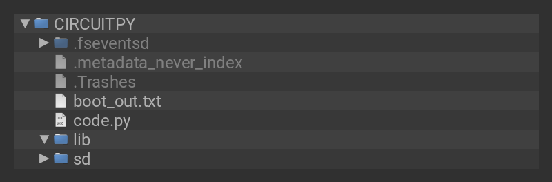
In the example below, click the Download Project Bundle button below to download the necessary libraries and the code.py file in a zip file. Extract the contents of the zip file, open the directory CircuitPython_Essentials/Pin_Map_Script/ and then click on the directory that matches the version of CircuitPython you're using and copy the contents of that directory to your CIRCUITPY drive.
Your CIRCUITPY
# SPDX-FileCopyrightText: 2020 anecdata for Adafruit Industries
# SPDX-FileCopyrightText: 2021 Neradoc for Adafruit Industries
# SPDX-FileCopyrightText: 2021-2023 Kattni Rembor for Adafruit Industries
# SPDX-FileCopyrightText: 2023 Dan Halbert for Adafruit Industries
#
# SPDX-License-Identifier: MIT

"""CircuitPython Essentials Pin Map Script"""
import microcontroller
import board
try:
    import cyw43  # raspberrypi
except ImportError:
    cyw43 = None

board_pins = []
for pin in dir(microcontroller.pin):
    if (isinstance(getattr(microcontroller.pin, pin), microcontroller.Pin) or
        (cyw43 and isinstance(getattr(microcontroller.pin, pin), cyw43.CywPin))):
        pins = []
        for alias in dir(board):
            if getattr(board, alias) is getattr(microcontroller.pin, pin):
                pins.append(f"board.{alias}")
        # Add the original GPIO name, in parentheses.
        if pins:
            # Only include pins that are in board.
            pins.append(f"({str(pin)})")
            board_pins.append(" ".join(pins))

for pins in sorted(board_pins):
    print(pins)
Here is the result when this script is run on QT Py SAMD21:

Each line represents a single pin. Find the line containing the pin name that's labeled on the physical board, and you'll find the other names available for that pin. For example, the first pin on the board is labeled A0. The first line in the output is board.A0 board.D0 (PA02). This means that you can access pin A0 in CircuitPython using both board.A0 and board.D0.
The pins in parentheses are the microcontroller pin names. See the next section for more info on those.
You'll notice there are two "pins" that aren't labeled on the board but appear in the list: board.NEOPIXEL and board.NEOPIXEL_POWER. Many boards have several of these special pins that give you access to built-in board hardware, such as an LED or an on-board sensor. The QT Py SAMD21 only has one on-board extra piece of hardware, a NeoPixel LED, so there's only the one available in the list. But you can also control whether or not power is applied to the NeoPixel, so there's a separate pin for that.
That's all there is to figuring out the available names for a pin on a compatible microcontroller board in CircuitPython!
Microcontroller Pin Names
The pin names available to you in the CircuitPython board module are not the same as the names of the pins on the microcontroller itself. The board pin names are aliases to the microcontroller pin names. If you look at the datasheet for your microcontroller, you'll likely find a pinout with a series of pin names, such as "PA18" or "GPIO5". If you want to get to the actual microcontroller pin name in CircuitPython, you'll need the microcontroller.pin module. As with board, you can run dir(microcontroller.pin) in the REPL to receive a list of the microcontroller pin names.

CircuitPython Built-In Modules
There is a set of modules used in most CircuitPython programs. One or more of these modules is always used in projects involving hardware. Often hardware requires installing a separate library from the Adafruit CircuitPython Bundle. But, if you try to find board or digitalio in the same bundle, you'll come up lacking. So, where do these modules come from? They're built into CircuitPython! You can find an comprehensive list of built-in CircuitPython modules and the technical details of their functionality from CircuitPython here and the Python-like modules included here. However, not every module is available for every board due to size constraints or hardware limitations. How do you find out what modules are available for your board?
There are two options for this. You can check the support matrix, and search for your board by name. Or, you can use the REPL.
Plug in your board, connect to the serial console and enter the REPL. Type the following command.
help("modules")

That's it! You now know two ways to find all of the modules built into CircuitPython for your compatible microcontroller board.
Page last edited June 11, 2025
Arduino IDE Setup
The first thing you will need to do is to download the latest release of the Arduino IDE. You will need to be using version 1.8 or higher for this guide
To use the ESP32-S2/S3 with Arduino, you'll need to follow the steps below for your operating system. You can also check out the Espressif Arduino repository for the most up to date details on how to install it.
After you have downloaded and installed the latest version of Arduino IDE, you will need to start the IDE and navigate to the Preferences menu. You can access it from the File menu in Windows or Linux, or the Arduino menu on OS X.

A dialog will pop up just like the one shown below.

We will be adding a URL to the new Additional Boards Manager URLs option. The list of URLs is comma separated, and you will only have to add each URL once. New Adafruit boards and updates to existing boards will automatically be picked up by the Board Manager each time it is opened. The URLs point to index files that the Board Manager uses to build the list of available & installed boards.
To find the most up to date list of URLs you can add, you can visit the list of third party board URLs on the Arduino IDE wiki. We will only need to add one URL to the IDE in this example, but you can add multiple URLS by separating them with commas. Copy and paste the link below into the Additional Boards Manager URLs option in the Arduino IDE preferences.
https://raw.githubusercontent.com/espressif/arduino-esp32/gh-pages/package_esp32_index.json

If you're an advanced hacker and want the 'bleeding edge' release that may have fixes (or bugs!) you can check out the dev url instead:
https://raw.githubusercontent.com/espressif/arduino-esp32/gh-pages/package_esp32_dev_index.json
If you have multiple boards you want to support, say ESP8266 and Adafruit, have both URLs in the text box separated by a comma (,)
Once done click OK to save the new preference settings.
The next step is to actually install the Board Support Package (BSP). Go to the Tools → Board → Board Manager submenu. A dialog should come up with various BSPs. Search for esp32. Choose the latest version, which may be later than the version shown in the screenshot below.

Click the Install button and wait for it to finish. Once it is finished, you can close the dialog.
In the Tools → Board submenu you should see ESP32 Arduino and in that dropdown it should contain the ESP32 boards along with all the latest ESP32-S2/S3 boards.
Look for the board called Adafruit MatrixPortal ESP32-S3.

Manually Resetting ESP32-S3 Boards
Due to an issue in the Espressif code base, boards with an ESP32-S3 need to be manually reset after uploading code from the Arduino IDE. After your code has been uploaded to the ESP32-S3, press the reset button. After pressing the reset button, your code will begin running.
For additional information, you can track the issue on GitHub in the arduino-esp32 repository.
Page last edited June 11, 2025
Using with Arduino IDE
Blink
Now you can upload your first blink sketch!
Plug in the ESP32-S2/S3 board and wait for it to be recognized by the OS (just takes a few seconds).
Select ESP32-S2/S3 Board in Arduino IDE


On the Arduino IDE, click:
Tools -> Board -> ESP32 Arduino -> Your Adafruit ESP32-S2/S3 board
The screenshot shows Metro S2 but you may have a different board. Make sure the name matches the exact product you purchased. If you don't see your board, make sure you have the latest version of the ESP32 board support package
Before we upload a sketch, place your ESP32-S2/S3 board into ROM bootloader mode.
Look for the Reset button and a second DFU / BOOT0 button
HOLD down the DFU/Boot0 button while you click Reset. Then release DFU/Boot0 button
The GIF shows a Metro S2 but your board may look different. It will still have BOOT and Reset buttons somewhere
It should appear under Tools -> Port as ESP32-S2/S3 Dev Module.

// the setup function runs once when you press reset or power the board
void setup() {
  // initialize built in LED pin as an output.
  pinMode(LED_BUILTIN, OUTPUT);
  // initialize USB serial converter so we have a port created
  Serial.begin();
}

// the loop function runs over and over again forever
void loop() {
  digitalWrite(LED_BUILTIN, HIGH);   // turn the LED on (HIGH is the voltage level)
  delay(1000);              // wait for a second
  digitalWrite(LED_BUILTIN, LOW);    // turn the LED off by making the voltage LOW
  delay(1000);              // wait for a second
}
And click upload! After uploading, you may see something like this:

And click upload! After uploading, you may see something like this, warning you that we could not get out of reset.
This is normal! Press the RESET button on your board to launch the sketch
That's it, you will be able to see the red LED blink. You will also see a new serial port created.
You may call Serial.begin(); in your sketch to create the serial port so don't forget it, it is not required for other Arduinos or previous ESP boards!

You can now select the new serial port name which will be different than the bootloader serial port. Arduino IDE will try to use auto-reset to automatically put the board into bootloader mode when you ask it to upload new code
If you ever DON'T see a serial port, or something is not working out with upload you can always manually enter bootloader mode:
- Reset board into ROM bootloader with DFU/BOOT0 + Reset buttons
- Select the ESP32S2/S3 Dev Board ROM bootloader serial port in Tools->Port menu
- Upload sketch
- Click reset button to launch code
Page last edited June 11, 2025
Arduino Blink
The first and most basic program you can upload to your Arduino is the classic Blink sketch. This takes something on the board and makes it, well, blink! On and off. It's a great way to make sure everything is working and you're uploading your sketch to the right board and right configuration.
When all else fails, you can always come back to Blink!
Pre-Flight Check: Get Arduino IDE & Hardware Set Up
This lesson assumes you have Arduino IDE set up. This is a generalized checklist, some elements may not apply to your hardware. If you haven't yet, check the previous steps in the guide to make sure you:
- Install the very latest Arduino IDE for Desktop (not all boards are supported by the Web IDE so we don't recommend it).
- Install any board support packages (BSP) required for your hardware. Some boards are built in defaults on the IDE, but lots are not! You may need to install plug-in support which is called the BSP.
- Get a Data/Sync USB cable for connecting your hardware. A significant amount of problems folks have stem from not having a USB cable with data pins. Yes, these cursed cables roam the land, making your life hard. If you find a USB cable that doesn't work for data/sync, throw it away immediately! There is no need to keep it around, cables are very inexpensive these days.
- Install any drivers required - If you have a board with a FTDI or CP210x chip, you may need to get separate drivers. If your board has native USB, it probably doesn't need anything. After installing, reboot to make sure the driver sinks in.
- Connect the board to your computer. If your board has a power LED, make sure its lit. Is there a power switch? Make sure its turned On!
Start up Arduino IDE and Select Board/Port
OK now you are prepared! Open the Arduino IDE on your computer. Now you have to tell the IDE what board you are using, and how you want to connect to it.
In the IDE find the Tools menu. You will use this to select the board. If you switch boards, you must switch the selection! So always double-check before you upload code in a new session.


Then in the new window, copy and paste this text:
int led = LED_BUILTIN;

void setup() {
  // Some boards work best if we also make a serial connection
  Serial.begin(115200);

  // set LED to be an output pin
  pinMode(led, OUTPUT);
}

void loop() {
  // Say hi!
  Serial.println("Hello!");

  digitalWrite(led, HIGH);   // turn the LED on (HIGH is the voltage level)
  delay(500);                // wait for a half second
  digitalWrite(led, LOW);    // turn the LED off by making the voltage LOW
  delay(500);                // wait for a half second
}
One note you'll see is that we reference the LED with the constant LED_BUILTIN rather than a number. That's because, historically, the built in LED was on pin 13 for Arduinos. But in the decades since, boards don't always have a pin 13, or maybe it could not be used for an LED. So the LED could have moved to another pin. It's best to use LED_BUILTIN so you don't get the pin number confused!
Verify (Compile) Sketch
OK now you can click the Verify button to convert the sketch into binary data to be uploaded to the board.
Note that Verifying a sketch is the same as Compiling a sketch - so we will use the words interchangeably

During verification/compilation, the computer will do a bunch of work to collect all the libraries and code and the results will appear in the bottom window of the IDE.

If something went wrong with compilation, you will get red warning/error text in the bottom window letting you know what the error was. It will also highlight the line with an error.
For example, here I had the wrong board selected - and the selected board does not have a built in LED!

Here's another common error, in my haste I forgot to add a ; at the end of a line. The compiler warns me that it's looking for one - note that the error is actually a few lines up!

On success you will see something like this white text output and the message Done compiling. in the message area.

Upload Sketch
Once the code is verified/compiling cleanly you can upload it to your board. Click the Upload button.

The IDE will try to compile the sketch again for good measure, then it will try to connect to the board and upload a the file.
This is actually one of the hardest parts for beginners because it's where a lot of things can go wrong.
However, lets start with what it looks like on success! Here's what your board upload process looks like when it goes right:

Often times you will get a warning like this, which is kind of vague:
No device found on COM66 (or whatever port is selected)An error occurred while uploading the sketch

This could be a few things.
First up, check again that you have the correct board selected! Many electronics boards have very similar names or look, and often times folks grab a board different from what they thought.
If you're positive the right board is selected, we recommend the next step is to put the board into manual bootloading mode.
Native USB and manual bootloading
Historically, microcontroller boards contained two chips: the main micro chip (say, ATmega328 or ESP8266 or ESP32) and a separate chip for USB interface that would be used for bootloading (a CH430, FT232, CP210x, etc). With these older designs, the microcontroller is put into a bootloading state for uploading code by the separate chip. It allows for easier uploading but is more expensive as two chips are needed, and also the microcontroller can't act like a keyboard or disk drive.
Modern chips often have 'native' USB - that means that there is no separate chip for USB interface. It's all in one! Great for cost savings, simplicity of design, reduced size and more control. However, it means the chip must be self-aware enough to be able to put itself into bootload/upload mode on its own. That's fine 99% of the time but is very likely you will at some point get the board into an odd state that makes it too confused to bootload.
Before continuing we really, really suggest turning on Verbose Upload messages, it will help in this process because you will be able to see what the IDE is trying to do. It's a checkbox in the Preferences menu.

Enter Manual Bootload Mode
OK now you know it's probably time to try manual bootloading. No problem! Here is how you do that for this board:
Before you start, make sure your MatrixPortal S3 is plugged into USB port to your computer using a data/sync cable. Charge-only cables will not work!
To enter the bootloader:
- Press and hold the Boot button down. Don't let go of it yet!
- Press and release the Reset button. You should still have the Boot button pressed while you do this.
- Now you can release the Boot button.
No USB drive will appear when you've entered the ROM bootloader. This is normal!
Once you are in manual bootload mode, go to the Tools menu, and make sure you have selected the bootloader serial port. It is almost certain that the serial port has changed now that the bootloader is enabled

Now you can try uploading again!

This time, you should have success!
After uploading this way, be sure to click the reset button - it sort of makes sure that the board got a good reset and will come back to life nicely.
It's also a good idea to try to re-upload the sketch again now that you've performed a manual bootload to get the chip into a good state. It should perform an auto-reset the second time, so you don't have to manually bootload again.

Once you've finished the re-upload, don't forget to press RESET and then select the old Port again!
Finally, a Blink!
OK it was a journey but now we're here and you can enjoy your blinking LED. Next up, try to change the delay between blinks and re-upload. It's a good way to make sure your upload process is smooth and practiced.
Page last edited June 11, 2025
I2C Scan Test
A lot of sensors, displays, and devices can connect over I2C. I2C is a 2-wire 'bus' that allows multiple devices to all connect on one set of pins so it's very convenient for wiring!
When using your board, you'll probably want to connect up I2C devices, and it can be a little tricky the first time. The best way to debug I2C is go through a checklist and then perform an I2C scan
Common I2C Connectivity Issues
- Have you connected four wires (at a minimum) for each I2C device? Power the device with whatever is the logic level of your microcontroller board (probably 3.3V), then a ground wire, and a SCL clock wire, and and a SDA data wire.
- If you're using a STEMMA QT board - check if the power LED is lit. It's usually a green LED to the left side of the board.
- Does the STEMMA QT/I2C port have switchable power or pullups? To reduce power, some boards have the ability to cut power to I2C devices or the pullup resistors. Check the documentation if you have to do something special to turn on the power or pullups.
- If you are using a DIY I2C device, do you have pullup resistors? Many boards do not have pullup resistors built in and they are required! We suggest any common 2.2K to 10K resistors. You'll need two: one each connects from SDA to positive power, and SCL to positive power. Again, positive power (a.k.a VCC, VDD or V+) is often 3.3V
- Do you have an address collision? You can only have one board per address. So you cannot, say, connect two AHT20's to one I2C port because they have the same address and will interfere. Check the sensor or documentation for the address. Sometimes there are ways to adjust the address.
- Does your board have multiple I2C ports? Historically, boards only came with one. But nowadays you can have two or even three! This can help solve the "hey, but what if I want two devices with the same address" problem: just put one on each bus.
- Are you hot-plugging devices? I2C does not support dynamic re-connection, you cannot connect and disconnect sensors as you please. They should all be connected on boot and not change. (Only exception is if you're using a hot-plug assistant but that'll cost you).
- Are you keeping the total bus length reasonable? I2C was designed for maybe 6" max length. We like to push that with plug-n-play cables, but really please keep them as short as possible! (Only exception is if you're using an active bus extender).
MatrixPortal S3 I2C Setup
The MatrixPortal S3 only has one I2C port, Wire, that is on the STEMMA QT connector.
It does have a built in LIS3DH accelerometer that is listening on address 0x19, so that address cannot be used by other devices.
Perform an I2C scan!
Install TestBed Library
To scan I2C, the Adafruit TestBed library is used. This library and example just makes the scan a little easier to run because it takes care of some of the basics. You will need to add support by installing the library. Good news: it is very easy to do it. Go to the Arduino Library Manager.

Search for TestBed and install the Adafruit TestBed library

Now open up the I2C Scan example

// SPDX-FileCopyrightText: 2023 Carter Nelson for Adafruit Industries
//
// SPDX-License-Identifier: MIT
// --------------------------------------
// i2c_scanner
//
// Modified from https://playground.arduino.cc/Main/I2cScanner/
// --------------------------------------

#include <Wire.h>

// Set I2C bus to use: Wire, Wire1, etc.
#define WIRE Wire

void setup() {
  WIRE.begin();

  Serial.begin(9600);
  while (!Serial)
     delay(10);
  Serial.println("\nI2C Scanner");
}


void loop() {
  byte error, address;
  int nDevices;

  Serial.println("Scanning...");

  nDevices = 0;
  for(address = 1; address < 127; address++ )
  {
    // The i2c_scanner uses the return value of
    // the Write.endTransmisstion to see if
    // a device did acknowledge to the address.
    WIRE.beginTransmission(address);
    error = WIRE.endTransmission();

    if (error == 0)
    {
      Serial.print("I2C device found at address 0x");
      if (address<16)
        Serial.print("0");
      Serial.print(address,HEX);
      Serial.println("  !");

      nDevices++;
    }
    else if (error==4)
    {
      Serial.print("Unknown error at address 0x");
      if (address<16)
        Serial.print("0");
      Serial.println(address,HEX);
    }
  }
  if (nDevices == 0)
    Serial.println("No I2C devices found\n");
  else
    Serial.println("done\n");

  delay(5000);           // wait 5 seconds for next scan
}
Wire up I2C device
While the examples here will be using the Adafruit MCP9808, a high accuracy temperature sensor, the overall process is the same for just about any I2C sensor or device.
The first thing you'll want to do is get the sensor connected so your board has I2C to talk to.


Wiring the MCP9808
The MCP9808 comes with a STEMMA QT connector, which makes wiring it up quite simple and solder-free.

Now upload the scanning sketch to your microcontroller and open the serial port to see the output. You should see something like this:

Page last edited June 11, 2025
WiFi Test
Thanksfully if you have ESP32 sketches, they'll 'just work' with variations of ESP32. You can find a wide range of examples in the File->Examples->Examples for Adafruit Metro ESP32-S2 subheading (the name of the board may vary so it could be "Examples for Adafruit Feather ESP32 V2" etc)

Let's start by scanning the local networks.
Load up the WiFiScan example under Examples->Examples for YOUR BOARDNAME->WiFi->WiFiScan

And upload this example to your board. The ESP32 should scan and find WiFi networks around you.
For ESP32, open the serial monitor, to see the scan begin.
For ESP32-S2, -S3 and -C3, don't forget you have to click Reset after uploading through the ROM bootloader. Then select the new USB Serial port created by the ESP32. It will take a few seconds for the board to complete the scan.

If you can not scan any networks, check your power supply. You need a solid power supply in order for the ESP32 to not brown out. A skinny USB cable or drained battery can cause issues.
WiFi Connection Test
Now that you can scan networks around you, its time to connect to the Internet!
Copy the example below and paste it into the Arduino IDE:
// SPDX-FileCopyrightText: 2020 Brent Rubell for Adafruit Industries
//
// SPDX-License-Identifier: MIT


/*
  Web client

 This sketch connects to a website (wifitest.adafruit.com/testwifi/index.html)
 using the WiFi module.

 This example is written for a network using WPA encryption. For
 WEP or WPA, change the Wifi.begin() call accordingly.

 This example is written for a network using WPA encryption. For
 WEP or WPA, change the Wifi.begin() call accordingly.

 created 13 July 2010
 by dlf (Metodo2 srl)
 modified 31 May 2012
 by Tom Igoe
 */

#include <WiFi.h>

// Enter your WiFi SSID and password
char ssid[] = "YOUR_SSID";             // your network SSID (name)
char pass[] = "YOUR_SSID_PASSWORD";    // your network password (use for WPA, or use as key for WEP)
int keyIndex = 0;                      // your network key Index number (needed only for WEP)

int status = WL_IDLE_STATUS;
// if you don't want to use DNS (and reduce your sketch size)
// use the numeric IP instead of the name for the server:
//IPAddress server(74,125,232,128);  // numeric IP for Google (no DNS)

char server[] = "wifitest.adafruit.com";    // name address for adafruit test
char path[]   = "/testwifi/index.html";

// Initialize the Ethernet client library
// with the IP address and port of the server
// that you want to connect to (port 80 is default for HTTP):
WiFiClient client;

void setup() {
  //Initialize serial and wait for port to open:
  Serial.begin(115200);
  while (!Serial) {
    ; // wait for serial port to connect. Needed for native USB port only
  }

  // attempt to connect to Wifi network:
  Serial.print("Attempting to connect to SSID: ");
  Serial.println(ssid);

  WiFi.begin(ssid, pass);
  while (WiFi.status() != WL_CONNECTED) {
      delay(500);
      Serial.print(".");
  }

  Serial.println("");
  Serial.println("Connected to WiFi");
  printWifiStatus();

  Serial.println("\nStarting connection to server...");
  // if you get a connection, report back via serial:
  if (client.connect(server, 80)) {
    Serial.println("connected to server");
    // Make a HTTP request:
    client.print("GET "); client.print(path); client.println(" HTTP/1.1");
    client.print("Host: "); client.println(server);
    client.println("Connection: close");
    client.println();
  }
}

void loop() {
  // if there are incoming bytes available
  // from the server, read them and print them:
  while (client.available()) {
    char c = client.read();
    Serial.write(c);
  }

  // if the server's disconnected, stop the client:
  if (!client.connected()) {
    Serial.println();
    Serial.println("disconnecting from server.");
    client.stop();

    // do nothing forevermore:
    while (true) {
      delay(100);
    }
  }
}


void printWifiStatus() {
  // print the SSID of the network you're attached to:
  Serial.print("SSID: ");
  Serial.println(WiFi.SSID());

  // print your board's IP address:
  IPAddress ip = WiFi.localIP();
  Serial.print("IP Address: ");
  Serial.println(ip);

  // print the received signal strength:
  long rssi = WiFi.RSSI();
  Serial.print("signal strength (RSSI):");
  Serial.print(rssi);
  Serial.println(" dBm");
}
NOTE: You must change the SECRET_SSID and SECRET_PASS in the example code to your WiFi SSID and password before uploading this to your board.

After you've set it correctly, upload and check the serial monitor. You should see the following. If not, go back, check wiring, power and your SSID/password

setup() with:
WiFi.setTxPower(WIFI_POWER_15dBm);
and confirm it with:
WiFi.getTxPower();
Secure Connection Example
Many servers today do not allow non-SSL connectivity. Lucky for you the ESP32 has a great TLS/SSL stack so you can have that all taken care of for you. Here's an example of a using a secure WiFi connection to connect to the Twitter API.
Copy and paste it into the Arduino IDE:
// SPDX-FileCopyrightText: 2015 Arturo Guadalupi
// SPDX-FileCopyrightText: 2020 Brent Rubell for Adafruit Industries
//
// SPDX-License-Identifier: MIT

/*
This example creates a client object that connects and transfers
data using always SSL.

It is compatible with the methods normally related to plain
connections, like client.connect(host, port).

Written by Arturo Guadalupi
last revision November 2015

*/

#include <WiFiClientSecure.h>
#include <WiFi.h>

// Enter your WiFi SSID and password
char ssid[] = "YOUR_SSID";             // your network SSID (name)
char pass[] = "YOUR_SSID_PASSWORD";    // your network password (use for WPA, or use as key for WEP)
int keyIndex = 0;                      // your network key Index number (needed only for WEP)

int status = WL_IDLE_STATUS;
// if you don't want to use DNS (and reduce your sketch size)
// use the numeric IP instead of the name for the server:
//IPAddress server(74,125,232,128);  // numeric IP for Google (no DNS)

#define SERVER "cdn.syndication.twimg.com"
#define PATH   "/widgets/followbutton/info.json?screen_names=adafruit"

// Initialize the SSL client library
// with the IP address and port of the server
// that you want to connect to (port 443 is default for HTTPS):
WiFiClientSecure client;

void setup() {
  //Initialize serial and wait for port to open:
  Serial.begin(115200);
  while (!Serial) {
    ; // wait for serial port to connect. Needed for native USB port only
  }

  // attempt to connect to Wifi network:
  Serial.print("Attempting to connect to SSID: ");
  Serial.println(ssid);

  WiFi.begin(ssid, pass);
  while (WiFi.status() != WL_CONNECTED) {
      delay(500);
      Serial.print(".");
  }

  Serial.println("");
  Serial.println("Connected to WiFi");
  printWifiStatus();

  client.setInsecure(); // don't use a root cert

  Serial.println("\nStarting connection to server...");
  // if you get a connection, report back via serial:
  if (client.connect(SERVER, 443)) {
    Serial.println("connected to server");
    // Make a HTTP request:
    client.println("GET " PATH " HTTP/1.1");
    client.println("Host: " SERVER);
    client.println("Connection: close");
    client.println();
  }
}

uint32_t bytes = 0;

void loop() {
  // if there are incoming bytes available
  // from the server, read them and print them:
  while (client.available()) {
    char c = client.read();
    Serial.write(c);
    bytes++;
  }

  // if the server's disconnected, stop the client:
  if (!client.connected()) {
    Serial.println();
    Serial.println("disconnecting from server.");
    client.stop();
    Serial.print("Read "); Serial.print(bytes); Serial.println(" bytes");

    // do nothing forevermore:
    while (true);
  }
}


void printWifiStatus() {
  // print the SSID of the network you're attached to:
  Serial.print("SSID: ");
  Serial.println(WiFi.SSID());

  // print your board's IP address:
  IPAddress ip = WiFi.localIP();
  Serial.print("IP Address: ");
  Serial.println(ip);

  // print the received signal strength:
  long rssi = WiFi.RSSI();
  Serial.print("signal strength (RSSI):");
  Serial.print(rssi);
  Serial.println(" dBm");
}
As before, update the ssid and password first, then upload the example to your board.
Note we use WiFiClientSecure client instead of WiFiClient client; to require a SSL connection!

Page last edited June 11, 2025
Usage with Adafruit IO
The ESP32-S2/S3 is an affordable, all-in-one, option for connecting your projects to the internet using our IoT platform, Adafruit IO.
- For more information and guides about Adafruit IO, check out the Adafruit IO Basics Series.
In the Arduino IDE, navigate to Sketch -> Include Library->Manage Libraries...

Enter Adafruit IO Arduino into the search box, and click Install on the Adafruit IO Arduino library option to install version 4.0.0 or higher.

When asked to install dependencies, click Install all.

If you do not already have an Adafruit IO account, create one now. Next, navigate to the Adafruit IO Dashboards page.
We'll create a dashboard to visualize and interact with the data being sent between your ESP32-S2/S3 board and Adafruit IO.


- Click the New Dashboard button.
- Name your dashboard My ESP32-S2 or My ESP32-S3 depending on your board.
- Your new dashboard should appear in the list.
- Click the link to be brought to your new dashboard.
We'll want to turn the board's LED on or off from Adafruit IO. To do this, we'll need to add a toggle button to our dashboard.


- Click the cog at the top right hand corner of your dashboard.
- In the dashboard settings dropdown, click Create New Block.
- Select the toggle block.
- Under My Feeds, enter led as a feed name. Click Create.
- Choose the led feed to connect it to the toggle block. Click Next step.


Next up, we'll want to display button press data from your board on Adafruit IO. To do this, we'll add a gauge block to the Adafruit IO dashboard. A gauge is a read only block type that shows a fixed range of values.


- Click the cog at the top right hand corner of your dashboard.
- In the dashboard settings dropdown, click Create New Block.
- Select the gauge block.
- Under My Feeds, enter button as a feed name.
- Click Create.
-
Choose the button feed to connect it to the toggle block.
- Click Next step.

Under block settings,
- Change Block Title to Button Value
- Change Gauge Min Value to 0, the button's state when it's off
- Change Gauge Max Value to 1, the button's state when it's on
- Click Create block
Your dashboard should look like the following:

For this example, you will need to open the adafruitio_26_led_btn example included with the Adafruit IO Arduino library. In the Arduino IDE, navigate to File -> Examples -> Adafruit IO Arduino -> adafruitio_26_led_btn.
Before uploading this code to the ESP32-S2/S3, you'll need to add your network and Adafruit IO credentials. Click on the config.h tab in the sketch.
Obtain your Adafruit IO Credentials from navigating to io.adafruit.com and clicking My Key. Copy and paste these credentials next to IO_USERNAME and IO_KEY.

Enter your network credentials next to WIFI_SSID and WIFI_PASS.

setup() with:
WiFi.setTxPower(WIFI_POWER_15dBm);
and confirm it with:
WiFi.getTxPower();
Click the Upload button to upload your sketch to the ESP32-S2/S3. After uploading, press the RESET button on your board to launch the sketch.
Open the Arduino Serial monitor and navigate to the Adafruit IO dashboard you created. You should see the gauge response to button press and the board's LED light up in response to the Toggle Switch block.
You should also see the ESP32-S2/S3's LED turning on and off when the LED is toggled:
Page last edited June 11, 2025
Arduino Sand Demo
We have a Sand/Pixel Dust demo available for the MatrixPortal that runs in Arduino. Below is the code to run it. The demo is also available as an example in the Arduino Protomatter library.
/* ----------------------------------------------------------------------
"Pixel dust" Protomatter library example. As written, this is
SPECIFICALLY FOR THE ADAFRUIT MATRIXPORTAL with 64x32 pixel matrix.
Change "HEIGHT" below for 64x64 matrix. Could also be adapted to other
Protomatter-capable boards with an attached LIS3DH accelerometer.

PLEASE SEE THE "simple" EXAMPLE FOR AN INTRODUCTORY SKETCH,
or "doublebuffer" for animation basics.
------------------------------------------------------------------------- */

#include <Wire.h>                 // For I2C communication
#include <Adafruit_LIS3DH.h>      // For accelerometer
#include <Adafruit_PixelDust.h>   // For sand simulation
#include <Adafruit_Protomatter.h> // For RGB matrix

#define HEIGHT  32 // Matrix height (pixels) - SET TO 64 FOR 64x64 MATRIX!
#define WIDTH   64 // Matrix width (pixels)
#define MAX_FPS 45 // Maximum redraw rate, frames/second

#if defined(_VARIANT_MATRIXPORTAL_M4_) // MatrixPortal M4
uint8_t rgbPins[]  = {7, 8, 9, 10, 11, 12};
uint8_t addrPins[] = {17, 18, 19, 20, 21};
uint8_t clockPin   = 14;
uint8_t latchPin   = 15;
uint8_t oePin      = 16;
#else // MatrixPortal ESP32-S3
uint8_t rgbPins[]  = {42, 41, 40, 38, 39, 37};
uint8_t addrPins[] = {45, 36, 48, 35, 21};
uint8_t clockPin   = 2;
uint8_t latchPin   = 47;
uint8_t oePin      = 14;
#endif

#if HEIGHT == 16
#define NUM_ADDR_PINS 3
#elif HEIGHT == 32
#define NUM_ADDR_PINS 4
#elif HEIGHT == 64
#define NUM_ADDR_PINS 5
#endif

Adafruit_Protomatter matrix(
  WIDTH, 4, 1, rgbPins, NUM_ADDR_PINS, addrPins,
  clockPin, latchPin, oePin, true);

Adafruit_LIS3DH accel = Adafruit_LIS3DH();

#define N_COLORS   8
#define BOX_HEIGHT 8
#define N_GRAINS (BOX_HEIGHT*N_COLORS*8)
uint16_t colors[N_COLORS];

Adafruit_PixelDust sand(WIDTH, HEIGHT, N_GRAINS, 1, 128, false);

uint32_t prevTime = 0; // Used for frames-per-second throttle

// SETUP - RUNS ONCE AT PROGRAM START --------------------------------------

void err(int x) {
  uint8_t i;
  pinMode(LED_BUILTIN, OUTPUT);       // Using onboard LED
  for(i=1;;i++) {                     // Loop forever...
    digitalWrite(LED_BUILTIN, i & 1); // LED on/off blink to alert user
    delay(x);
  }
}

void setup(void) {
  Serial.begin(115200);
  //while (!Serial) delay(10);

  ProtomatterStatus status = matrix.begin();
  Serial.printf("Protomatter begin() status: %d\n", status);

  if (!sand.begin()) {
    Serial.println("Couldn't start sand");
    err(1000); // Slow blink = malloc error
  }

  if (!accel.begin(0x19)) {
    Serial.println("Couldn't find accelerometer");
    err(250);  // Fast bink = I2C error
  }
  accel.setRange(LIS3DH_RANGE_4_G);   // 2, 4, 8 or 16 G!

  //sand.randomize(); // Initialize random sand positions

  // Set up initial sand coordinates, in 8x8 blocks
  int n = 0;
  for(int i=0; i<N_COLORS; i++) {
    int xx = i * WIDTH / N_COLORS;
    int yy =  HEIGHT - BOX_HEIGHT;
    for(int y=0; y<BOX_HEIGHT; y++) {
      for(int x=0; x < WIDTH / N_COLORS; x++) {
        //Serial.printf("#%d -> (%d, %d)\n", n,  xx + x, yy + y);
        sand.setPosition(n++, xx + x, yy + y);
      }
    }
  }
  Serial.printf("%d total pixels\n", n);

  colors[0] = matrix.color565(64, 64, 64);  // Dark Gray
  colors[1] = matrix.color565(120, 79, 23); // Brown
  colors[2] = matrix.color565(228,  3,  3); // Red
  colors[3] = matrix.color565(255,140,  0); // Orange
  colors[4] = matrix.color565(255,237,  0); // Yellow
  colors[5] = matrix.color565(  0,128, 38); // Green
  colors[6] = matrix.color565(  0, 77,255); // Blue
  colors[7] = matrix.color565(117,  7,135); // Purple
}

// MAIN LOOP - RUNS ONCE PER FRAME OF ANIMATION ----------------------------

void loop() {
  // Limit the animation frame rate to MAX_FPS.  Because the subsequent sand
  // calculations are non-deterministic (don't always take the same amount
  // of time, depending on their current states), this helps ensure that
  // things like gravity appear constant in the simulation.
  uint32_t t;
  while(((t = micros()) - prevTime) < (1000000L / MAX_FPS));
  prevTime = t;

  // Read accelerometer...
  sensors_event_t event;
  accel.getEvent(&event);
  //Serial.printf("(%0.1f, %0.1f, %0.1f)\n", event.acceleration.x, event.acceleration.y, event.acceleration.z);

  double xx, yy, zz;
  xx = event.acceleration.x * 1000;
  yy = event.acceleration.y * 1000;
  zz = event.acceleration.z * 1000;

  // Run one frame of the simulation
  sand.iterate(xx, yy, zz);

  //sand.iterate(-accel.y, accel.x, accel.z);

  // Update pixel data in LED driver
  dimension_t x, y;
  matrix.fillScreen(0x0);
  for(int i=0; i<N_GRAINS ; i++) {
    sand.getPosition(i, &x, &y);
    int n = i / ((WIDTH / N_COLORS) * BOX_HEIGHT); // Color index
    uint16_t flakeColor = colors[n];
    matrix.drawPixel(x, y, flakeColor);
    //Serial.printf("(%d, %d)\n", x, y);
  }
  matrix.show(); // Copy data to matrix buffers
}
This sketch was written for a 64x32 pixel matrix but is easily modified for a 64x64 matrix!
Look for this line in the code:
#define HEIGHT 32 // Matrix height (pixels) - SET TO 64 FOR 64x64 MATRIX!
and change it to:
#define HEIGHT 64 // Matrix height (pixels) - SET TO 64 FOR 64x64 MATRIX!
Now upload the sketch to your Qualia S3and make sure a round display is connected. You may need to press the Reset button to reset the microcontroller. You should see a series of colored rectangles along the bottom. Go ahead and start moving the matrix around!
If you have a 3D Printer, be sure to check out the Matrix Portal Sand Handles guide.
Page last edited June 11, 2025
Migrating from MatrixPortal M4
If you have a project that was working on the MatrixPortal M4 and you would like it to work on the newer hardware, most of the features should work without needing to do a lot of modification. The path to updating your project will differ a bit depending on whether it was done using Arduino or CircuitPython.
In most cases, you will not need to update your hardware configuration, but there is one particular case where you may have to. If you were using DAC Audio output, this is no longer supported by the ESP32-S3. Instead it uses I2S audio output, so that part of your circuit would need to be changed.
Some of the other differences that may require code changes include:
- The WiFi is no longer a coprocessor, but is integrated into the ESP32-S3 itself.
- The flash memory is no longer a separate chip, which may have required a separate library in Arduino.
- The ESP32-S3 has A LOT more flash memory and RAM, so if you were limited by these on the MatrixPortal M4, you no longer need to worry.
- The ESP32-S3 pins are much more flexible and most of them are capable of DigitalIO and analog input in addition to any other special functions. This includes the TXO and RXI pins.
If your project uses CircuitPython and the MatrixPortal library, most of the changes should carry over automatically. If you are accessing some of the lower level functions directly, you may need to change the instantiation if it is expecting to access the WiFi coprocessor directly.
If your project uses Arduino, you will likely need to change pin numbers as some of the pin names have changed.
Page last edited June 11, 2025
Install UF2 Bootloader
The MatrixPortal S3 ships with a UF2 bootloader which allows the board to show up as MATRXS3BOOT when you double-tap the reset button, and enables you to drag and drop UF2 files to update the firmware.
On ESP32-S2 and ESP32-S3, there is no bootloader protection for the UF2 bootloader. That means it is possible to erase or damage the UF2 bootloader, especially if you upload an Arduino sketch to an ESP32-S2/S3 board that doesn't "know" there's a bootloader it should not overwrite!
It turns out, however, the ESP32-S2/S3 comes with a second bootloader: the ROM bootloader. Thanks to the ROM bootloader, you don't have to worry about damaging the UF2 bootloader. The ROM bootloader can never be disabled or erased, so its always there if you need it! You can simply re-load the UF2 bootloader from the ROM bootloader.
If your UF2 bootloader ends up damaged or overwritten, you can follow the steps found in the Factory Reset and Bootloader Repair section of the Factory Reset page in this guide.
Once completed, you'll return to where the board was when you opened the package. Then you'll be back in business, and able to continue with your existing plans!
Page last edited June 11, 2025
Factory Reset
The MatrixPortal S3 microcontroller ships running a self test demo It's lovely, but you probably had other plans for the board. As you start working with your board, you may want to return to the original code to begin again, or you may find your board gets into a bad state. Either way, this page has you covered.
You're probably used to seeing the MATRXS3BOOT drive when loading CircuitPython or Arduino. The MATRXS3BOOT drive is part of the UF2 bootloader, and allows you to drag and drop files, such as CircuitPython. However, on the ESP32-S3 the UF2 bootloader can become damaged.
If you have a bootloader still installed - which means you can double-click to get the MATRXS3BOOT drive to appear, then you can simply drag this UF2 file over to the BOOT drive.
To enter UF2 bootloader mode, plug in the board into a USB cable with data/sync capability. Press the reset button once, wait till the RGB LED turns purple, then quickly press the reset button again. (You are doing a "slow double-click"). Then drag this file over:
Your board is now back to its factory-shipped state, running again with the original factory program. You can now begin again with your plans for your board.
What if you tried double-tapping the reset button, and you still can't get into the UF2 bootloader? Whether your board shipped without the UF2 bootloader, or something damaged it, this section has you covered.
It turns out, however, the ESP32-S2/S3 comes with a second, built-in, bootloader, the ROM bootloader, which cannot be erased or damaged. You can always reload the UF2 bootloader using the ROM bootloader.
There are three ways to do a factory reset and bootloader repair. The first and easiest is to use the OPEN INSTALLER button on the page for your board on circuitpython.org. This method requires no manual downloads and guides you through the steps interactively. We highly recommend this method as your first choice.
The second method is to use the browser-based Adafruit WebSerial ESPTool, and the third is to use esptool.py via the command line.
For both OPEN INSTALLER and the Adafruit WebSerial tool, you must use Firefox 151 or later, or Chrome 89 or later.

The OPEN INSTALLER button on circuitpython.org is the easiest way to install or update the UF2 bootloader. See the Learn Guide Using the OPEN INSTALLER Button on circuitpython.org for all the details.
Adafruit WebSerial ESPTool and esptool.py Methods for UF2 Bootloader Installation
The other methods for bootloader installation require you to download the bootloader yourself. The next section walks you through the prerequisite steps needed for both of these methods.
Clik on the green button below to download the .bin file you need (there may be more than one listed), and save wherever is convenient for you. You will need to be able to access the file from the Adafruit WebSerial ESPTool or another upload method.
Step 2. Enter ROM bootloader mode
Entering the ROM bootloader is easy. Complete the following steps.
Before you start, make sure your ESP32-S2/S3 is plugged into USB port to your computer using a data/sync cable. Charge-only cables will not work!
To enter the bootloader:
- Press and hold the BOOT/DFU button down. Don't let go of it yet!
- Press and release the Reset button. You should still have the BOOT/DFU button pressed while you do this.
- Now you can release the BOOT/DFU button.
No USB drive will appear when you've entered the ROM bootloader. This is normal!
Now that you've downloaded the .bin file and entered the ROM bootloader, you're ready to continue installing the UF2 bootloader. The next two sections walk you through using the Adafruit WebSerial ESPTool (Alternative A) or esptool.py (Alternative B).
(There is also an Alternative C below, using the Arduino IDE, but it is less desirable, because it does not allow you to choose the bootloader that will be used.)
This method uses the Adafruit WebSerial ESPTool through a browser. Adafruit WebSerial ESPTool is a web-based option for programming ESP32-S2/S3 boards. It allows you to erase the the microcontroller flash and program up to four files at different offsets.
You have to use a browser that supports WebSerial for this to work. FIrefox versions 151 or later and and Chrome versions 89 or later work. Safari and is not supported because they don't have support for Web Serial functionality.
Follow the steps below to flash the UF2 bootloader.
Connect
You should have plugged in only the ESP32-S2/S3 that you intend to flash. That way there's no confusion in picking the proper port when it's time!

In the Chrome browser visit https://adafruit.github.io/Adafruit_WebSerial_ESPTool/. You should see something like the image shown.
Leave the No reset for Passthrough updates toggle off.

Press the Connect button in the top right of the web browser. You will get a pop up asking you to select the COM or Serial port.
Remember, you should remove all other USB devices so only the ESP32-S2/S3 board is attached, that way there's no confusion over multiple ports!
On some systems, such as MacOS, there may be additional system ports that appear in the list.

The JavaScript code will now try to connect to the ROM bootloader. It may timeout for a bit until it succeeds. On success, you will see that it is Connected and will print out a unique MAC address identifying the board along with other information that was detected.


To erase the contents, click the Erase button. You will be prompted whether you want to continue. Click OK to continue or if you changed your mind, just click cancel.

You'll see "Erasing flash memory. Please wait..." This will eventually be followed by "Finished." and the amount of time it took to erase.
Do not disconnect! Immediately continue on to programming the ESP32-S2/S3.
Programming the ESP32-S2/S3 can be done with up to four files at different locations, but with the board-specific bootloader .bin file, which you should have downloaded under Step 1 on this page, you only need to use one file.

Click on the first Choose a file.... (The tool will only attempt to program buttons with a file and a unique location.) Then, select the bootloader .bin file you downloaded in Step 1 that matches your board.
Verify that the Offset box next to the file location you used is (0x) 0.

Once you choose a file, the button text will change to match your filename. You can then select the Program button to begin flashing.

Once completed, you can skip down to the section titled Reset the Board.
Once you have entered ROM bootloader mode, you can then use Espressif's esptool program to communicate with the chip! esptool is the 'official' programming tool and is the most common/complete way to program an ESP chip.
Install esptool.py
You will need to use the command line or Terminal to install and run esptool.
You will also need to have pip and Python installed (any version!).
Install the latest version using pip (you may be able to run pip without the 3 depending on your setup):
pip3 install --upgrade esptool
Then, you can run:
esptool.py
Test the Installation
Run esptool.py in a new terminal/command line and verify you get something like the below:

Find the Serial Port
First, you need to determine the name of the serial port you board has when it's plugged in and ROM bootloader mode.
- For Windows, it will be a COM port, such as
COM5. Look in Device Manager -> Ports. - For macOS, you can do
ls /dev/tty.*in a Terminal to find the names of the serial ports. - For Linux, you can do ls
/dev/tty*in a terminal window. The name is often /dev/ttyACM0 or similar.
If you are not sure you've found the right port, unplug the board, and see if the port disappears.
For more information on determining serial ports, follow these links for help on Windows, macOS, or Linux.
Connect
Run the following command, replacing the identifier after --port with the COMxx, /dev/cu.usbmodemxx or /dev/ttySxx you found above.
For example, if you're using Windows, and you think the board is on COM88, type this following:
esptool.py --port COM88 chip_id
You should get a notice that it connected over that port and found an ESP32-S2/S3.

Erase the Flash
Before programming the board, it is a good idea to erase the flash. Run the following command.
esptool.py --port COM88 erase_flash
You must be connected (by running the command in the previous section) for this command to work as shown.

Flash the UF2 Bootloader
Run this command and replace the serial port name with your matching port and the file you just downloaded
esptool.py --port COM88 write_flash 0x0 tinyuf2-some-board-0.32.0-combined.bin
Don't forget to change the --port name to match.
tinyuf2-some-board-0.32.0-combined.bin.
There might be a bit of a 'wait' when programming, where it doesn't seem like it's working. Give it a minute, it has to erase the old flash code which can cause it to seem like it's not running.
You'll finally get an output like this:

Once completed, you can continue to the next section.
The board should restart automatically, and start up the UF2 bootloader. If not, press the reset button to start the bootloader.
If you have the board plugged into a 64x32 LED Matrix, you should see some shapes and lines in Red, Green, Blue, and White along with the text ADAFRUIT in white at the top.
You've successfully returned installed the UF2 bootloader on your board. If you now want to return the board to a factory reset state, follow the instructions at the top of the page to Install the Factory Reset Firmware UF2.
We suggest updating to Chrome 89 or newer, as Web Serial is enabled by default.
If you must continue using an older version of Chrome, follow these steps to enable Web Serial.

If you receive an error like the one shown when you visit the Adafruit WebSerial ESPTool site, you're likely running an older version of Chrome.
You must be using Chrome 78 or later to use Web Serial.

To enable Web Serial in Chrome versions 78 through 88:
- Visit chrome://flags from within Chrome.
- Find and enable the Experimental Web Platform features
- Restart Chrome
Step 3: Alternative C. The Flash an Arduino Sketch Method
This section outlines flashing an Arduino sketch onto your ESP32-S2/S3 board, which automatically installs the UF2 bootloader as well. However, it does not allow you to choose which UF2 bootloader to install, so Alternative A or B above are preferred.
Arduino IDE Setup
If you don't already have the Arduino IDE installed, the first thing you will need to do is to download the latest release of the Arduino IDE. ESP32-S2/S3 requires version 1.8 or higher. Click the link to download the latest.
After you have downloaded and installed the latest version of Arduino IDE, you will need to start the IDE and navigate to the Preferences menu. You can access it from the File > Preferences menu in Windows or Linux, or the Arduino > Preferences menu on OS X.
The Preferences window will open.
In the Additional Boards Manager URLs field, you'll want to add a new URL. The list of URLs is comma separated, and you will only have to add each URL once. The URLs point to index files that the Board Manager uses to build the list of available & installed boards.
Copy the following URL.
https://raw.githubusercontent.com/espressif/arduino-esp32/gh-pages/package_esp32_dev_index.json
Add the URL to the the Additional Boards Manager URLs field (highlighted in red below).

Click OK to save and close Preferences.
In the Tools > Boards menu you should see the ESP32 Arduino menu. In the expanded menu, it should contain the ESP32 boards along with all the latest ESP32-S2 boards.
Now that your IDE is setup, you can continue on to loading the sketch.
In the Tools > Boards menu you should see the ESP32 Arduino menu. In the expanded menu, look for the menu option for the Adafruit MatrixPortal ESP32-S3, and click on it to choose it.
Open the Blink sketch by clicking through File > Examples > 01.Basics > Blink.

For the Arduino IDE to upload TinyUF2 you must select a TinyUF2 partition layout, under the Tools > Partition Scheme menu.
If you have a 4MB board, won't be doing Over-The-Air firmware updates (OTA), or are unsure, then choose the 'No OTA' TinyUF2 entry.

Finally, click Upload from the sketch window.

Once successfully uploaded, the little red LED will begin blinking once every second. At that point, you can now enter the bootloader.
Page last edited June 11, 2025
USB Power
If powering a MatrixPortal and associated LED matrix solely through the USB port, you might encounter a situation where the image appears stable when only a few pixels are lit, but brighter images with more pixels lit may exhibit “ghosting” or “sparkling” artifacts.
This is not a software bug. Please do not report it as a software bug.
This is a USB power issue. It does not affect everyone because there are so many different USB power sources and permutations. What follows is an explanation and some workarounds.
Not all USB ports are created equal. The ports on many computers are designed to provide 5 Volts at a maximum of 1 Ampere (1A)…or sometimes as little as 500 mA (0.5A). Likewise with USB wall chargers: small ones might deliver 1A or less, and even beefier models seldom exceed 2–2.5A.
LED matrices can be power hungry. And the more pixels in use, the hungrier they are. When a matrix demands more power than is available through the USB port, this can result in a momentary brown-out condition, and the sort of visual glitches described above. This can be exacerbated by cheap, thin USB cables that have a lot of resistance.
Complicating issues, the voltage and current from a USB port are not rock steady. This is especially true of USB battery banks. The buck/boost converter circuit in these devices creates a sort of “buzz” in the output; on average it might be 5V 2A, but the instantaneous voltage and current will oscillate around this. This is no problem for a typical steady use like charging a phone, but LED matrices are weird…it’s not just that they’re hungry, but like the supply voltage, the LED current draw also oscillates they’re actually flashed on and off hundreds of times a second to produce an image.
Some Solutions to Try
If you encounter the aforementioned phenomenon, here are some things to try, starting from the very simple and working our way up…
- Try swapping the USB cable if the one you have seems thin. That free cable included for charging a mouse or Bluetooth speaker might be unsuitable for the amount of current we need. Look for something beefy, like a tablet or laptop charging cable. Those luxury braided cables are also sometimes a sign of “substance.”
- If powering from a computer’s USB port: try using a sizable (2A or better) USB wall charger instead.
- If powering from a USB wall charger or USB battery bank: Try swapping out for any others you might have on hand. More current (higher amperage) is always nice, but that’s not the whole story. As explained above, the output filtering (or lack of) can affect the steadiness of the output voltage and current.
Those are the easy “switch something out” fixes. If none of those address the issue, now things get progressively more complex…
- Try powering the MatrixPortal and LED matrix separately: USB for the MatrixPortal, and a 5V DC “wall wart” supply (2A or preferably more) for the matrix, using one of these screw terminal power adapters (i.e. don’t use the screw terminals on the MatrixPortal, use this instead):

- If the project must be powered from a USB battery bank and you’ve already tested some others: try powering the LED matrix and the MatrixPortal separately. This might involve two power banks, or one with multiple ports might suffice (most enforce per-port current limits), you’ll need to experiment. Cables exist to convert USB type A or C to a DC plug that’s compatible with the screw terminal adapter above — one would power the LED matrix through this, and the MatrixPortal through a normal USB cable. Just make sure the cable provides 5V output; some are “booster” cables to higher voltages that could destroy the matrix.
- If nothing else seems to work, the last line of defense is better filtering on the power supply output. This involves adding one or more capacitors across the + and – terminals until the image stabilizes. Unfortunately there is no one-size-fits-all solution here…it requires experimentation with an assortment of caps on hand. One might start with a 1000 µF cap, and work up or down from there. If something seems promising but imperfect, two or more with different values might be needed in parallel (e.g. 100 µF + 1000 µF).

This photo shows NeoPixels, but the principle is exactly the same: capacitance helps smooth out fluctuations in the power supply. Look for something at least 10V rated (higher is OK) and values from 50 µF to 2000 µF. Folks who’ve been doing electronics for a while usually end up with a little parts drawer of random caps, so maybe you (or someone you know, or a local maker space) already have something suitable.
Page last edited June 11, 2025
Downloads
Schematic
Note: the ALS-PT19 light sense phototransistor is NOT part of the final design for this board, even though it appears on the schematic. We apologize for any confusion.


Page last edited June 11, 2025


